-
-
March 4, 2024 at 8:42 pm
Tim Bomer
SubscriberHi,
Currently I'm working on a simulation of a flexure system in ANSYS Mechanical.
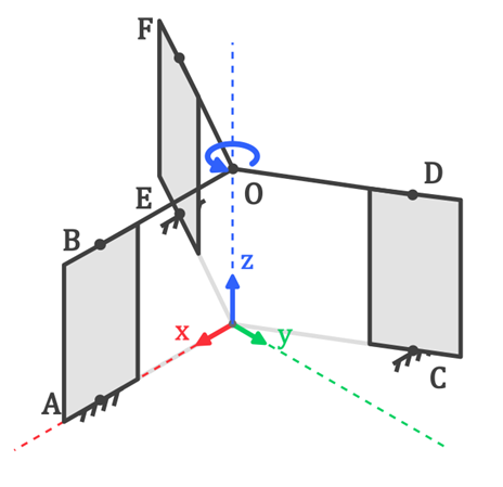
To give you some context, the complete flexure system is Illustrated:
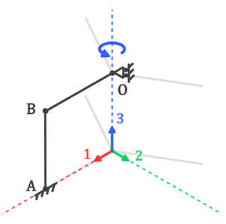
It consists of three thin sheet flexures, all fixed to the world at the bottom and with an rigid plattorm on top. The system allows for a rotation around the Z axis as the flexures deform in their compliant direction. To simplify the system I've used the symmetry and came up with the resulting model (AB is still a flexure):
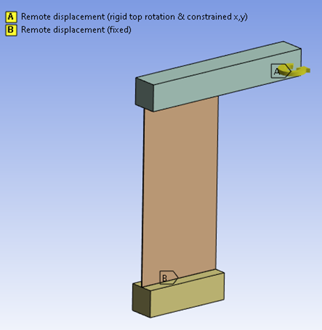
I've modeled this ANSYS Mechanical with these simulation parameters:
- large deflections ON
- Fixed boundary condition at the bottom
- remote displacement at the top: prescribed zrot (2.5 deg) free z displacement, fixed x displ, y displ, xrot, y rot
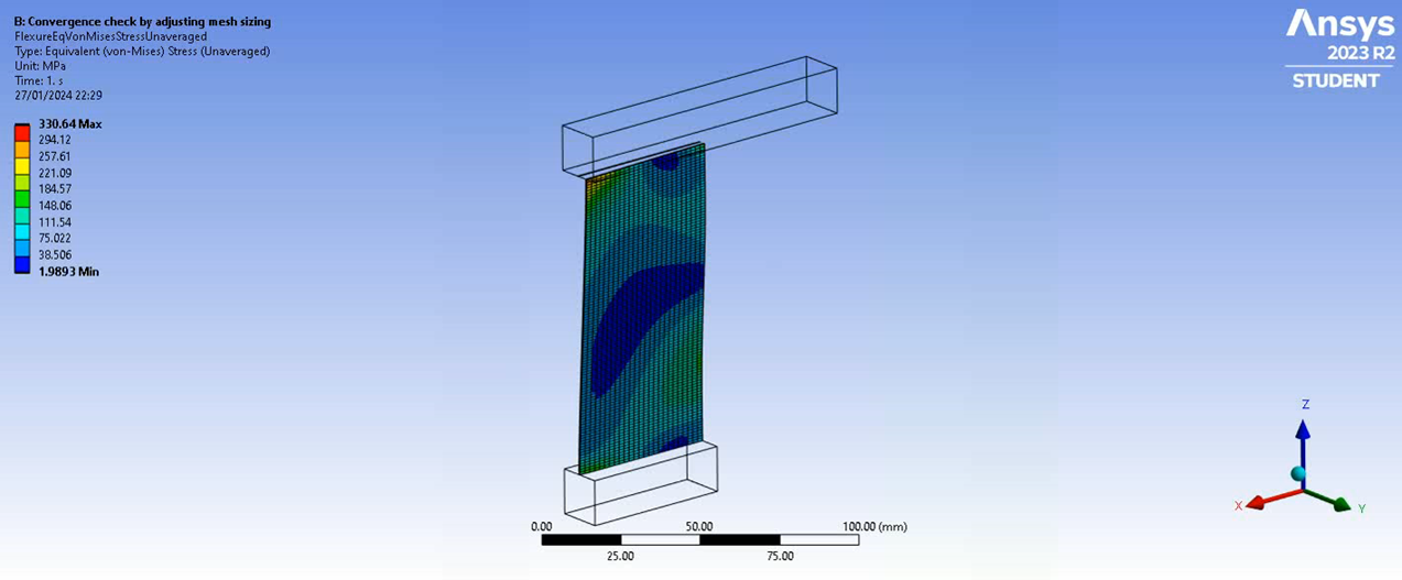
I'm interested in the stress gradient & the maximum von mises stress of the flexure over a specified rotation like this:
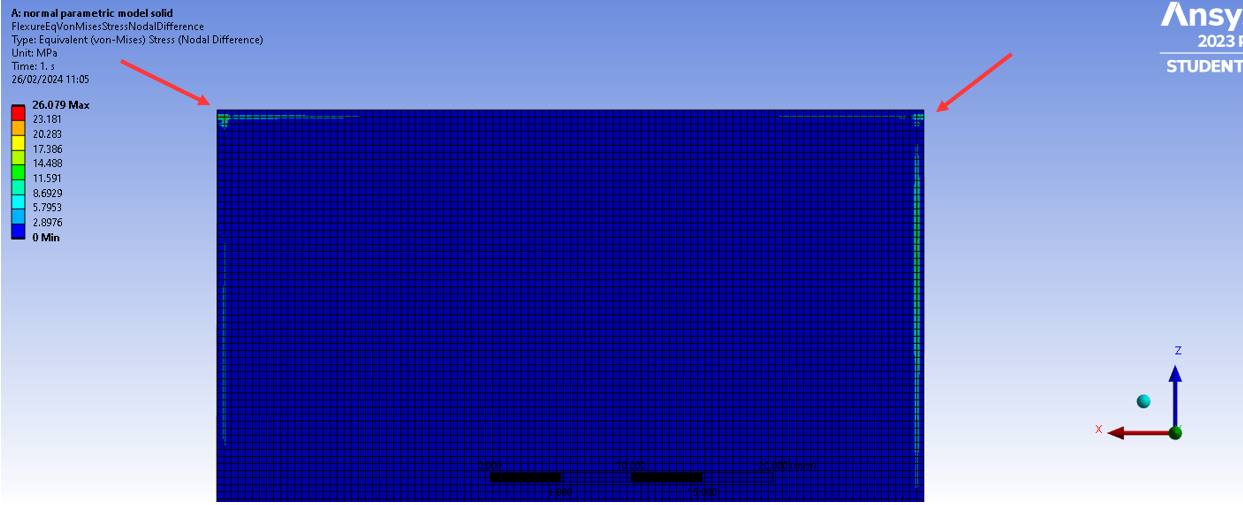
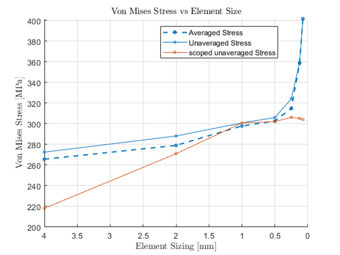
I've modeled the system with solid elements and have done a manual convergence study by measuring the averaged and unaveraged stress, while reducing the element size. There was quite a difference between the averaged/unaveraged results so to dive a into this I've plotted the nodal differences. What i found was these lines of nodal differences at the outer edges of the flexure. And this line would shift with the element size.
So i found that this line of high nodal difference is always within the first row (top bottom) or column (left& right side) of the elements. So as I move from a larger element to smaller the nodal differences shift. I.e. if i plot this at 2mm element size (width vs height) this line will be located 2mm from the top/bottom or side. and if i plot this with a mesh that has 0.5mm element size (as in the picture) the nodal difference line is located at 0.5mm.
Unfortunately this high nodal difference line lies really close to the location with maximum stress and therefore I can't just ignore it.
So my theory is that this has something to do with the harsh boundary conditions that are applied. As I'm still a student and I'm not that experienced with these simulation I was wondering about your point of view & how you would deal with this problem. If you need any additional information, just let me know.
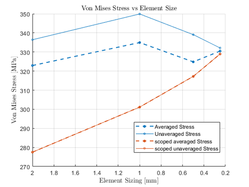
I've also made the same model using shell elements.The shell elements have the same issue. I could just ignore the outer elements by scoping. So as i reduce the element size I plot the stress results using a named selection that does not contain the outer edge of elements. For using shell elements i then obtain:
- large deflections ON
-
March 11, 2024 at 11:52 am
Ashish Khemka
Forum ModeratorHi,
This looks to be because of imposed boundary conditions. What if you try to study the stress leaving first two layers of elements near boundary conditions.
Regards,
Ashish Khemka
-
- The topic ‘Nodal difference lines that shift with element size’ is closed to new replies.


-
4693
-
1565
-
1386
-
1242
-
1021

© 2025 Copyright ANSYS, Inc. All rights reserved.

