-
-
March 4, 2024 at 8:14 am
Rommel Jr. Landicho
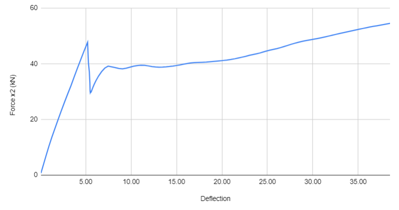
SubscriberHi everyone! I am modelling a Reinforced Concrete Beam subjected to a four point bending test. The nonlinear solution is already converging and some of the values are relatively close to my reference. Here are my concerns:
(1)
However, the force-deflection curve / stress-strain diagram shows a sudden decrease after reaching the yield stress and then gradually increases. It's not supposed to show sudden drops in strength after yielding, I expect it to increase continuously. Can someone suggest how I can fix this?
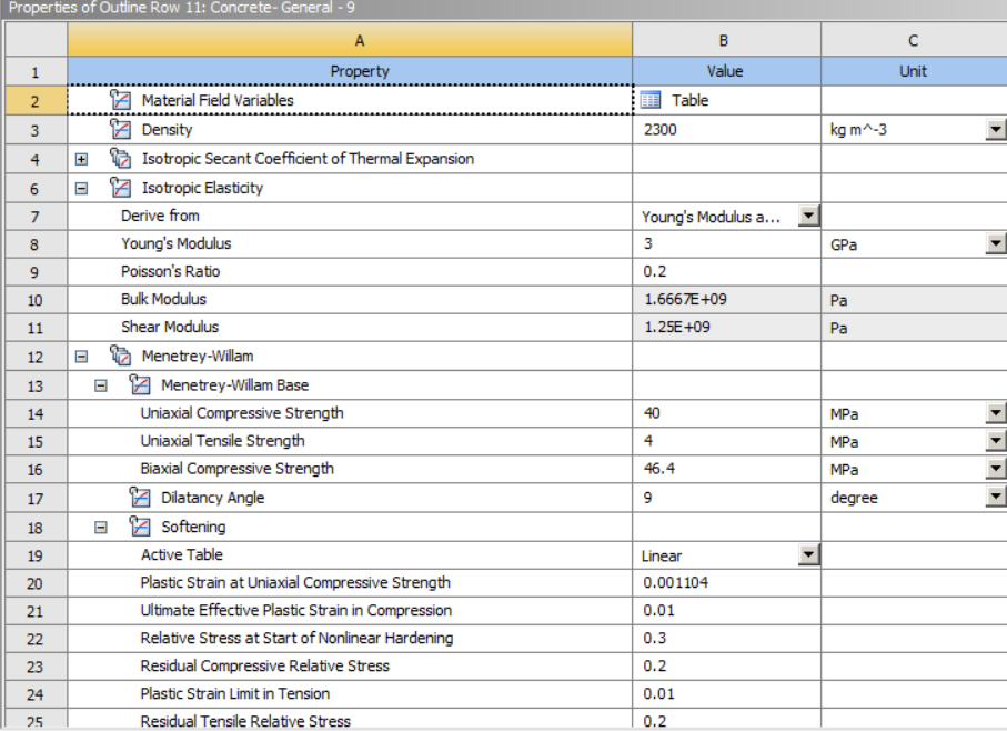
I used Menetrey Willam model for the concrete with the following parameters
I am also unsure if my boundary conditions are correct. I used an edge as a pin support (UX=UY=UZ= 0 and Rx = FREE RY=RZ=0) while the loading is a face with remote displacement (UX=UZ=0, UY = -7, Rx = FREE, RY = RZ = 0). I put a finer mesh at these conditions because there is too much strain in one element if I let it be the same as the other mesh.
I have also checked the stress-strain diagram of the rebars and it is correct. Do you have suggestions on how I can stop the sudden decrease after yielding?
(2) I noticed that when I change the mesh method and even the mesh size to smaller, it does not converge anymore. I expected that since my model converged, decreasing my mesh would yield more accurate results. Is this normal? How else can I do a mesh convergence test?
Any suggestions would be appreciated. Thank you!!
-
March 6, 2024 at 3:35 pm
John Doyle
Ansys EmployeeAt the point in the load history, where force reaction is highest, can you post process any plastic strain? If not, you might be seeing extrapolation of elastic stress and strain, from element integration points to nodes, just before yielding begins. If that is the case, try turning off all extrapolation by adding an MAPDL command 'ERESX,no' in the Environment Branch, to be executed just before the Solve.
Refining the mesh is putting element integration points closer to the outside surfaces and corner nodes. This is generally a good thing, but perhaps you are propagating very localized yielding in tension, causing convergence instability. With regards to mesh refinement and local plasticity, it can often be a tradeoff between accuracy and convergence stability. Also, sometimes switching to lower order elements with enhanced strain formulation, can help stabilize element distortion issues.
-
March 8, 2024 at 7:10 am
Rommel Jr. Landicho
SubscriberHi! Thanks for your help. I have tried adding the command. Although it changes the load deflection curve, there are still some drops. I tried varying the parameters and some variations remove the sudden drop, I am still trying to figure it out. However, I would like to ask another question regarding beam failure.
My model has fairly accurate results as compared with my reference load-deflection curve. However, I do not know how to determine when the beam will fail. In my reference study, the beam is supposed to crush due to flexure at a deflection of ~35 mm but my model continues to deflect at 50 mm (maybe even more if I increase my displacement control). How will I know if my model has failed due to flexure? What result will ANSYS give if my beam has crushed? Also, are there plots I can make to see its cracking or at least potential areas where cracking can occur?
Thanks!
-
-
March 8, 2024 at 3:49 pm
John Doyle
Ansys EmployeePerhaps you need more realistic displacement constraints on the bottom of the beam. They look like knife edges. The stress and strain will just diverge to infinitiy with mesh refinement.
-
March 10, 2024 at 9:22 am
Rommel Jr. Landicho
SubscriberHi! Thanks for your suggestion. I will try it. For the meantime, I am encountering another problem. I hope you could help here also.
Although my load-deflection curves are somewhat similar to that of my reference study, I am not sure how I can know if my beam has crushed or not. Am I the one to set my own criteria to decide whether the beam fails? Right now, I can only think of steel rebar yielding as a criteria -- that is, if the steel rebar reaches its yield strength (400 MPa), then I will assume that the beam fails. The problem here is the steel rebar yields at around 49 mm in my model while it should yield at 35 mm based on my reference study. Because of this, I am unable to accurately determine the maximum deflection that my beam can experience.
What can I do to correct this? Do you have suggestions on how I can know when my beam fails? I have read something about utilizing stress tools but I do not quite understand how I can use them to know if my beam fails.
-
-
- The topic ‘Different Stress-Strain Diagram of RC Beam’ is closed to new replies.


-
4959
-
1639
-
1386
-
1242
-
1021

© 2026 Copyright ANSYS, Inc. All rights reserved.


