-
-
February 20, 2024 at 10:35 pm
Anthony Bowers
SubscriberHello all!
I am trying to create a good quality mesh for a pipe with two bends (85 degrees) and a flow condtioner. I want a y+ < 5 for enhanced wall function with a realizable k-e turbulent model. However, I am struggling to obtain an acceptable orthogonality and skewness quantity with the inflation layer, first cell thickness, requirement.
Here are a few images of my flow domain.
What does the community suggest?
-
February 21, 2024 at 6:34 am
Keyur Kanade
Ansys EmployeeYou will need to define mesh sizing correctly.
Please check following link.
https://ansyshelp.ansys.com/account/secured?returnurl=/Views/Secured/corp/v221/en/wb_msh/ds_Sizing_Group.html
Also if you want y+<5 then if your surface mesh size is 1 mm try to get first layer of inflation of 0.1mm.
Please check following videos
Ansys Meshing Sizing:
https://www.youtube.com/watch?v=w4q6q8nKF3UAnsys Meshing: Meshing Methods:
https://www.youtube.com/watch?v=nEOC8rDnnRoAnsys Meshing: Inflation:
https://www.youtube.com/watch?v=lrEHXizrhC0Regards,
Keyur
How to access Ansys Online Help Document
Guidelines on the Student Community
Fluids Engineering Courses | Ansys Innovation Courses
-
February 21, 2024 at 3:40 pm
-
-
February 21, 2024 at 1:39 pm
Anthony Bowers
SubscriberHi Keyru,
Thanks for your response. While the first link did not work I will review the other links and post my questions here.
-
February 21, 2024 at 4:38 pm
Rob
Forum ModeratorI'd be more concerned with the jump in cell size at the end of the smaller pipes. I'm sure I've seen a similar geometry recently, if so, there are some suggestions in that thread.
-
February 21, 2024 at 5:09 pm
Anthony Bowers
SubscriberI have checked forums with key word of "peforated plate", "Flow conditioner", "mesh " and have not been able to find anything but I will keep looking!
Ideally, I'd like a mesh like this
I attempt a multizone for the larger pipes but it fails to decompose.. multizone only works for the smaller holes in the flow conditioner
-
-
February 21, 2024 at 5:16 pm
Rob
Forum Moderator/forum/forums/topic/design-modeler-for-fluid-simulaton/
I'd be inclined to use a tet/poly mesh in the complex part and sweep/multizone in the rest of the domain.
-
February 21, 2024 at 6:10 pm
-
-
February 22, 2024 at 9:31 am
Rob
Forum ModeratorIf you tet just the small tubes the inflation layer will break and do some very interesting things as they rejoin the main tube. This is why learning about decomposition is recommended: an old skill that becomes very useful in this sort of situation. If I had to use a hybrid tet & swept mesh I'd be meshing 5 volumes in total (if I counted correctly).
The mesh in "wanted" image looks like something I'd have built in GAMBIT 15-20 years ago. I wouldn't have used any inflation, and the refined section looks like it may have been adapted.
The warning is because you're not using the Worksheet (inside Meshing) to record the order inwhich you mesh things.
Finally, the tet mesh you've shown is awful. Inflation is just to get a reasonable resolution perpendicular to the wall with as few cells as possible. You also need to consider flow separation, cell aspect ratio (because the flow won't be perfectly aligned to the walls and jump in cell size: at best you've got the first cell height about right.
-
February 22, 2024 at 1:02 pm
Anthony Bowers
Subscriber
-
-
February 22, 2024 at 1:09 pm
Rob
Forum ModeratorThat's not how I'd decompose it. Sweeping the larger sections shouldn't need the splits.
-
February 22, 2024 at 1:19 pm
-
-
February 22, 2024 at 1:53 pm
Rob
Forum ModeratorThink about the advice so far. Splitting the smaller pipes at the ends makes using inflation mesh difficult. There's no need to split the long sections axially. So, how would you sweep most of the long pipe but also connect the smaller pipes so you can use inflation and tets?
I'm not able to just tell you as that's "specialist knowledge" and I don't want another conversation with Legal....
-
February 22, 2024 at 1:55 pm
Anthony Bowers
SubscriberOkay, I will take some time to think about this. Thank you for your guidance!
-
-
February 22, 2024 at 1:55 pm
Rob
Forum ModeratorSo, how could you use tets in some regions, swept mesh elsewhere? The image above (omitting the remainder of the model) would split into 3 bodies.
-
February 22, 2024 at 2:52 pm
Anthony Bowers
SubscriberOkay, I found a good video that I think exemplifies what you are talking about (
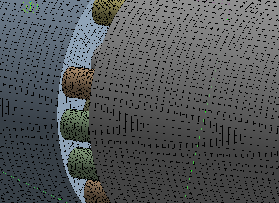
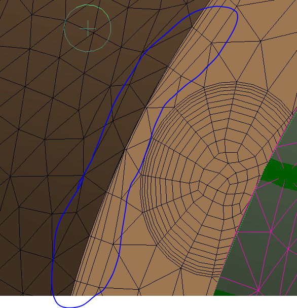
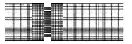
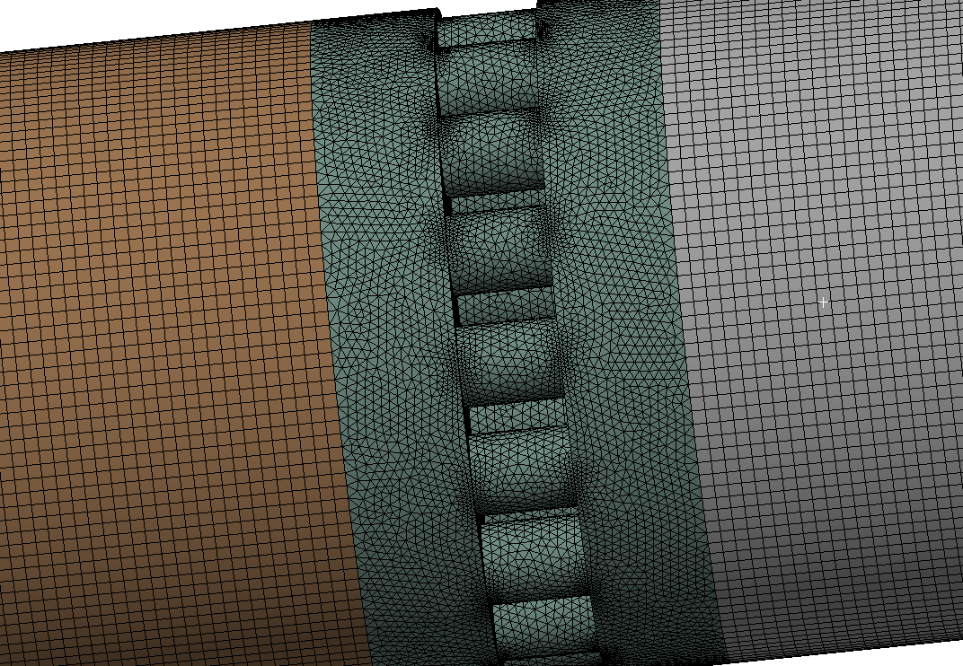
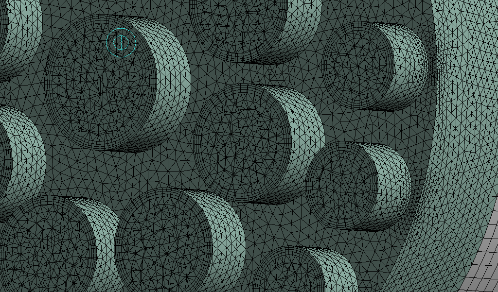
; Workbench Meshing Methods for CFD | ANSYS e-Learning | CAE Associates). However, this is giving me a non-conformal mesh, and with no imprints of the flow conditioners, on the pipe ends, I am unable to give the domain wall boundary condition. Should I accept that a non-conformal mesh will occur and deal with the loss of accuracy from the interpolation of domains? Again thank you Rob for your help, you are being very patient with me and I thoroughly appreciate it.
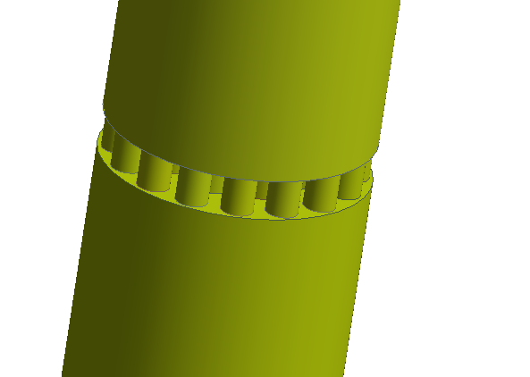
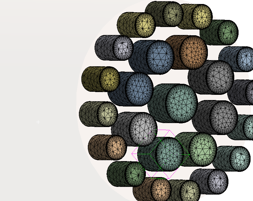
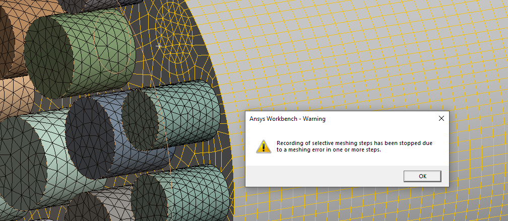
P.s,In that video, the user has the part separate, part 1 (containing 1 body), but he was able to get a conformal mesh without connections. I have mimicked this tutorial but when I import the mesh i (A) still have interface connections being read in; (B) obtaining a non-conformal mesh
-
-
February 22, 2024 at 2:59 pm
Rob
Forum ModeratorThe image shows exactly what I mean, thanks for finding that. You also need to use Share topology (SpaceClaim & Discovery) or form a multibody part (DesignModeler). Mesh the awkward bit first and then work away from that zone meshing one zone at a time (the order will be retained in the Worksheet if you switch that on).
-
February 22, 2024 at 3:55 pm
-
February 22, 2024 at 4:21 pm
Rob
Forum ModeratorI meant the video, your image only showed up now! Splitting like you have will cause problems. The error isn't the message you've shown, that's the warning that meshing has stopped. That may well be linked to inflation settings, Sweep doesn't use inflation in the same way as the tets.
-
February 22, 2024 at 6:48 pm
Anthony Bowers
SubscriberOkay, here is a huge update. I finally understood the object and decomposed the geometry as seen below.
I am able to get a Conformal mesh between the bodies, inflation on the larger pipe, and inflation in the smaller pipes.
This is what the section plane looks like when sliced down the middle of the FC
Now I am facing an orthogonality issue of 6e-02.
-
February 23, 2024 at 10:27 am
Rob
Forum ModeratorOK, on the mesh slice shown look for a blue-ish triangle. That will display whole elements and make it easier to see the cut plane. As you are using tet and prism focus on skewness. In meshing find the quality graph and you want to select cells with skew over about 0.9 to 0.95 then look at what's causing the poor quality.
Once you've fixed that I think you're sorted.
-
- The topic ‘Meshing Advice’ is closed to new replies.
-
6395
-
1906
-
1457
-
1308
-
1022
© 2026 Copyright ANSYS, Inc. All rights reserved.


