TAGGED: ansys-autodyn, erosion, Failure-Model, hourglass-energy, impact-analysis
-
-
February 19, 2024 at 3:13 pm
henrique.geraissate
SubscriberDear community,
First of all, I am sorry in advance for the long post. I am new to Explicit Dynamics and I would like some input from you so I can understand how correct my model is set up.
I am trying to analyze the impact of a rigid hollow cylinder against an Aluminum plate (Al 6061-T6, explicit materials library), using Autodyn. I went through most of the theory guide in the manual, but I am still not sure what are the best configurations for this type of analysis.
The plate is fixed on the top and bottom edges, and the cylinder hits it with 72m/s. No contacts are initially defined and body interaction settings is default (frictionless). The goal of my analysis is to define a minimum plate thickness to withstand the impact, and evaluate the force reaction to quantify the amount and size of screws that will be holding that plate.
I have run 6 different calculation scenarios, changing some key settings between each. These settings are: including or not material failure model (max effective plastic strain), element erosion and viscous coefficient of hourglass forces (HVC). The mesh is really coarse, just so I could run this scenarios in a short time.
The first two scenarios were without any material failure, just with different HVC values (0.1 and 0.05). Scenarios 3 and 4 include material failure at a defined max plastic strain (obtained from stress-strain curve). Finaly, the last two scenarios include both material failure + erosion (on material failure).
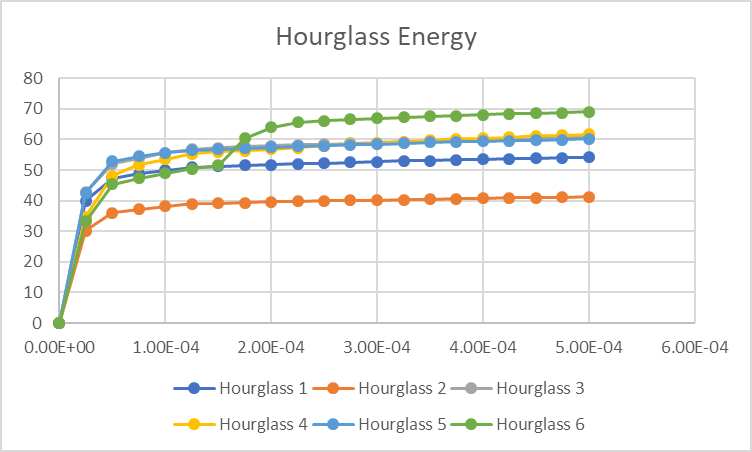
Scenarios 1 and 2 (the most conservative and likely artificially stiff models) show the highest plastic strain (even higher than failure criteria, of course) and a (expected) reduction on hourglass energy when decreasing the HVC, which corresponds to 9.6% and 7.3% of the plate internal energy. It also shows the highest reaction force.
3 and 4 (failure on plastic strain, no erosion) result in a "cap" of plastic strain based on the value I input as failure, a sligthly higher internal energy and a stable ratio of 10.5% hourglass energy contribution, even when changing the HVC.
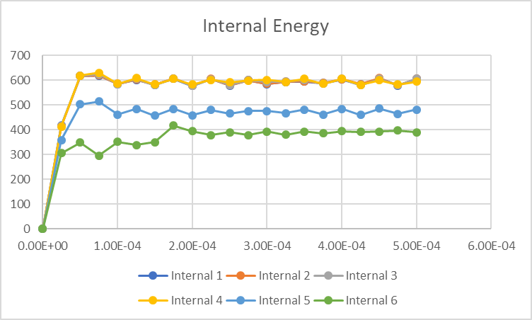
5 and 6 (failure + erosion) also cap the plastic strain, and show a huge decrease in the internal energy of the plate due to element erosion. From the around 600 J of the first four scenarios, it went to 500 J (HVC=0.1) and down to 400 J (HVC=0.05), bringing the hourglass ratio to 13% and 18%, respectively.
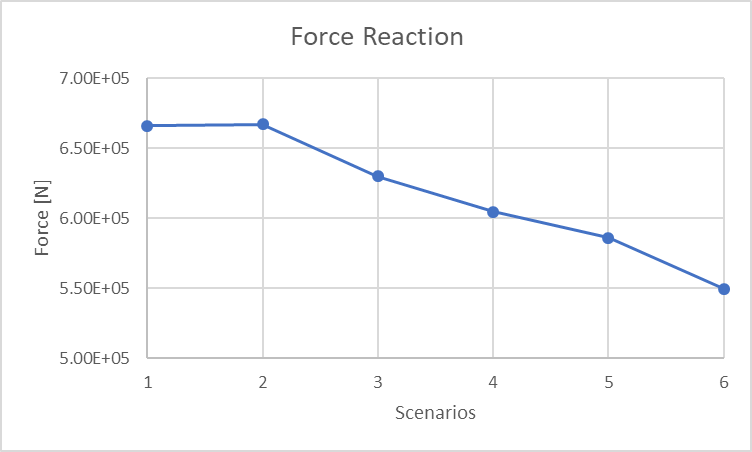
The reaction forces were also decreasing as I made the model "softer", from 670 kN in scenarios 1 and 2, to 550 kN in scenario 6.
Ok, now to the questions:
- I have a strain-stress curve from uniaxial test data, showing fracture on a plastic strain of 13%. I am using 11% as failure limit for the simulations. Does it even make sense to use data from such a simple test in a dynamic model?
- Does it make sense to use this failure criteria in a model dominated by compression stress?
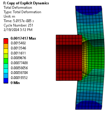
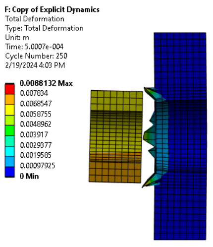
- When I leave failure ON but erosion OFF, the failed elements behave very weirdly after impact (see picture below). Why is that?
- Reducing the HVC value from scenario 3 to 4 did not improved the ratio between hourglass and internal energies. Why is that?
- I understand that erosion is a numerical approach to keep the time step reasonable. I can also see it clearly influencing the physics of my simulation in scenario 6, where, due to erosion, it seems like the cylinder has two impacts against the plate. Is there a clever way to use this feature in this type of simulation, or should I simply turn it off for good?
- Which scenario would you consider a valid one?
I left below some graphs comparing these scenarios, and I hope it helps to better understand.
Picture of the weird elements after failing:
Sorry once again for the long post, thanks in advance for whoever find the time to answer, and I am looking forward this discussion!
Best regards,
Henrique -
February 20, 2024 at 3:07 pm
Ram Gopisetti
Ansys EmployeeHi Henrique,
Let's back a bit and get the right understanding of what each of the parameters will do in a given model, material failure model (max effective plastic strain) and element erosion are interrelated where the erosion criteria can be material-based failure or by default it goes to geometric strain limit of 1.5.
The viscous coefficient for hourglass forces in explicit dynamics is a parameter that controls the amount of damping applied to hourglass modes in hexahedral solid elements and quadrilateral shell elements. Hourglass forces are artificial forces introduced in finite element analysis to prevent hourglassing, which is a type of numerical instability where elements can deform unrealistically without generating strain energy. The viscous coefficient usually varies between 0.05 and 0.15, with the default value being 0.1. The sum of the hourglass forces applied to an element is normally zero, which means that the momentum of the system is unaffected by hourglass forces.
So in short, HCV is a damping control, and the question is, for such a simple model why do you want to add or modify damping? , does your study need it or are you exploring the topic here?
Choosing the failure limit solely relies on the users, however, why use the 11 % failure limit when the test says 13 % even for this simple test?
I am not sure of your second question, but for every type of loading ( tensile, compression ) there are failure limits and distinctive.
Please check my point above about how erosion is considered when no failure is provided, in such scenarios you see the elements being stretched causing those shapes and in General, this practice is not recommended.
If lowering the HVC value did not result in an improvement in the ratio, it might be required to investigate alternative hourglass control techniques, modify the stiffness coefficient, or take into account the particular material characteristics and the kinds of simulation elements utilized.
I am not sure what you mean by two impacts, given that you model the problem with the initial velocity and right end time you should be able to get the right impacting behaviors, this is influencing the physics of your simulation, as it effectively alters the geometry and mass distribution of the model over time
I cannot suggest which scenario is correct as it conflicts with many of the pointers discussed above. Please revisit your problem.
Cheers, Ram
-
February 20, 2024 at 4:02 pm
henrique.geraissate
SubscriberHello Ram,
Thanks for your answer.
I am testing the different HVC values to understand how sensitive this simple model is to that parameter, and also because, with the default settings, I am achieving hourglass energy values greater than 10% of internal energy. I saw that the general recommendation is to keep it around 5%. From your question, I understand that you would not bother with that. Would mind explaining why? Anyway, I will try and explore other hourglass control settings just for the sake of it.
As for the failure criteria, I am using 11% because most of the data I found in literature was around that elongation at break. The data I have with the 13% is from a textbook solely for practice purposes.
I think I understand a bit better now what happen to the failed elements if no erosion is considered: as stated in the manual, after failure is detected, the element will no longer hold any tensile loads. So, if I understood correctly, if they are not eroded from calculation they will just keep deforming, without any resistance. And if applying a failure model without erosion is not recommended, I should either go for a model with no failure at all or I need to be able to accuretly define the failure model, is that it? I mean, maybe using some crack failure model or johnson-cook’s.
The two impacts: when the cylinder first touch the plate (first impact) it causes the elements on the plate to deform up to the failure limit, causing a whole layer (or few layers) of elements in the plate to be eroded. This leaves some “free space” for the cylinder to travel until it reaches the next layer of elements (second impact), which will then be able to absorb the collision without failing. This seems very non realistic to me. But while I was writing, it just occured that this might be probably a issue due to the coarse mesh, and refining it could maybe create a smoother effect. I will try that.
To make things more practical, I am now using a model with no failure criteria, and let the solver extrapolate the strain and stress based on the plasticity model (Johnson-Cook strength, in this case). And then I am simply evaluating the areas where the plastic strain is above 11%. I guess this is way more conservative and probably not as accurate, but I have the impression that it still give better overview (and maybe better physics representation) than using erosion. Could you please comment on that?
I hope I was clear enough! Looking forward to your answer.
Cheers,
Henrique -
February 23, 2024 at 1:39 pm
Ram Gopisetti
Ansys EmployeeHi Henrique,
I recommend you take the course on explicit dynamics to understand its physics, especially with the energy balance in Lesson 4 of the course given in the below link.
https://www.youtube.com/watch?v=oRulOsX7ijk
You need to define the failure model accurately, in fact, use the JC damage parameters rather than the added erosion criteria.
Cheers, Ram
-
- The topic ‘Questions on Explicit Dynamics Settings’ is closed to new replies.


-
5094
-
1824
-
1387
-
1248
-
1021

© 2026 Copyright ANSYS, Inc. All rights reserved.

