General Mechanical

General Mechanical

Topics related to Mechanical Enterprise, Motion, Additive Print and more.

Basic Interference fit

    • Norvegas25
      Subscriber

      Hi


      I'm trying to get an solution on Ansys workbench with the pressure that occurs from interference fit.  I have tried with basic models, where i have shaft & hole, but I can't manage to get the results to be similar to the formula. 


      Formula used :


      Young's modulus and Poisson ratio is the same for both shaft and hole, which is standard from ansys for constructional steel


      Shaft outer diameter is 32.03mm


      Hole outer diameter is 40 mm 


      Hole inner diameter is 32 mm


      Which should give 33.8 MPa, but i can't get similar results on Ansys. I would like to know If there is something I'm missing or missunderstanding, would be nice to get some tips about it. 


      I'm using method from this example:


      https://caeai.com/resources/simulating-interference-fits-ansys-e-learning


      The settings im running for contacts is : 


      Type:                         Frictionless


      Formulation:             Augmented Lagrange


      Detection Method:   Nodal-Projected Normal From Contact


      Normal Stiffness:      I've played around and tried different factors 


      Interface Treatment:  Add Offset, Ramped Effects


    • peteroznewman
      Subscriber

      How are you retrieving pressure from your model solution?


      How are you supporting the model, with planes of symmetry?


      Show your mesh.


      Did you make a 2D model or a 3D model?


      If you made a 2D model, did you use Plane Stress or Plane Strain?


      If you made a 3D model, are you retrieving pressure near the center of the length to avoid end effects?


      Did you create a cylindrical coordinate system?


      The figure shows a width w, but the formula is for an infinite length contact.


      Please state the value of Young's modulus and Poisson ratio you used.

    • Norvegas25
      Subscriber

      I'm quite new with Ansys, so here is what i know: 


      According to the video you get the pressure from the interference contact, with Normal stress on the shaft.


      This is an imported 3D modell file from SolidWorks. I did not create cylindrical coordinates system.


      With planes of symmetry supports you mean like boundary condition, fixed supports etc?  In that case i have no boudary conditions for that modell


      The figure with width W, is for further calculations to find the Force needed to , irrelevant for pressure calculations.  Page 2 of slide Link.


      Young's modulus = 200MPa  and Poisson ratio = 0.3 


      For my mesh i used:


      Default for whole assembly, Body sizing on 3mm for shaft (I focus only pressure that occurs on the shaft).


      Inflation on shaft with 0,1 transition ration, 5 layers and 1 growth rate and Face mesh on shaft. 


    • peteroznewman
      Subscriber

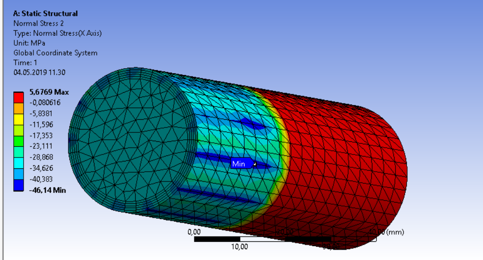
      1) You should use at least 4 elements through the thickness of the ring sleeve. One element is inadequate.


      2) If you make a Cylindrical Coordinate System then the X-axis will be radial and you will get a more uniform display. With the Global coordinate system, you get a high point along the X axis and a minimum point 90 degrees around the circumference.  You don't need a cylindrical coordinate system if you insert a Contact Tool in the Solution Branch and Insert a Pressure result.


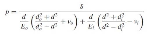
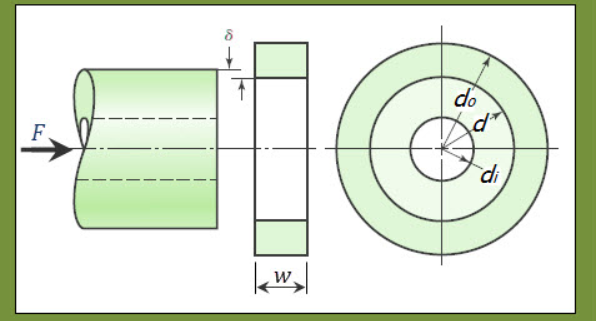
      3) The equation is for either plane stress or plane strain, which you can get in a 2D model. Do you know what were the assumptions in that equation?  If you make a 2D model, the surfaces must be in the XY plane and you must set the Geometry cell Property of Analysis Type to 2D in the Workbench interface before you transfer that geometry to Mechanical when you open the Model cell. 


      4) It will be better if you slice the model with 2 planes to make a 1/4 pie slice. Use a displacement BC to set just one displacement, the normal to the face, equal to zero.  This is true for both 2D and 3D.


      5) The penetration in the contact is less using Normal Lagrange than Augmented Lagrange.


      6) Your calculation of the expected Normal Stress (Pressure) is off by a factor of 1000.  The answer I got using the formula above and values you provided is 0.03375 MPa


      7) If I make a model using the methods I outline above, using Plane Stress equations, I get a Normal Stress of 0.03375 MPa, which is in near perfect agreement with the equation.  If I switch to Plane Strain equations, the Normal Stress is 0.0371 MPa.


Viewing 3 reply threads
  • The topic ‘Basic Interference fit’ is closed to new replies.