TAGGED: bug, eigenmode, fdtd, Feature request, s-matrix
-
-
February 11, 2024 at 2:54 pm
amitrotem2
SubscriberImagine two straight rectangular waveguides with ports along the propagation direction.
Each port sees a similar 2D slice, but can calculate the eigenmode with a different sign; mostly for the anti-symmetric mode.
I can see this when looking at the S-matrix from FDTD simulation.
What would be the best way to regularize that ?
How can I overlap the modes from different ports with the source port (in order to obtain this sign directly) ?
`expand` does not seem to hundle ports
-
February 12, 2024 at 6:56 pm
Guilin Sun
Ansys EmployeeSince the seed is random to calculate the modes, usually we cannot control the sign of the propagation, eg, real(neff). As long as the mode does not have artificial gain, the mode is physical even it propagates toward negative direction. Dues to numerical error, sometimes very small gain (negative (neff)) can be ignored.
Sometimes if you restart the simulation file, or slightly modify the mesh it can be improved.
You can import the mode source if the travelling direction cannot be satisfied, with the correct mode.
-
February 13, 2024 at 7:16 am
amitrotem2
SubscriberI not sure I understand; I'm talking about the sign of the eigen-mode; i.e. the sign of the electromagnetic field. Is it related to the sign of the eigen-value (
neff) ? Is the sign ofreal(neff)related to the relative sign between the electric and magnetic fields right ?I thought the sign of
real(neff)is always positive, unlessCORRECT BACKWARD PROPAGATING MODESis on which can switch the sign of neff in order to avoid artificial (numerical) gain from due to the sign ofimag(neff). Which, btw, does not seem to be synchronized with the injection direction of the source - If I want to inject a mode in theforwarddirection should I care about the sign ofneff. Maybe this is a topic for another post?Anyway, how can I extract these sign differences between (similar) modes calculated in different ports ? e.g., expand mode#1 from port#1 with mode#1 from port#2 ?
-
February 13, 2024 at 3:57 pm
Guilin Sun
Ansys EmployeeYes, you are right that real(neff) is related to E and H direction, recall that E cross H towards the propagation direction.
No, real(neff) is not necessarily positive!
Whether the injection is forward or backward, positive real(neff) means the mode propagates along the injection direction.
Mode profile is distributive, which is not exactly the same as a plane wave. and because in general mode can have complex field, you can use the real(E),real(H) with their respective components (lateral) to determine the direction of the fields. EHK always follows righthand tirad.
So I am not sure what is the purpose to get the sign difference of similar modes. You can plot vectorial fields to get some clue. expantion is to know the portion of the fields relative to the base mode profile.
vectorial fields have signs relative to the polarization (TE or TM). I do not know any textbooks discussing the sign of a mode.
-
February 13, 2024 at 7:55 pm
amitrotem2
SubscriberWhen the eigen-mode solver gives me (real valued for simplicity)
E,Hpair, the pairs-E,H,E,-H, and-E,-Hare also a solutions to the eigen-value problem. Which one does the solver outputs?These are the same physical solution up to a phase, or reversed propagation direction?
When calculating the S-matrix of a system (using S parameter sweep), the choice of these signs affects the sign of the matrix elements.
So, how can I know if my matrix element is
S_jkor-S_jk? -
February 13, 2024 at 9:20 pm
Guilin Sun
Ansys EmployeeNo, only one set is the correct solution, since E cross H is toward the propagation direction.
The solution will give you correct phase value if there is any. However since it is not a plane wave so we do not expect to have only one phase value cross the mode profile, due to numerical errors.
Usually the sign of S matrix is not important. It is the absolute value that matters. The phase can change if you place the monitor/port at different locations.
If you still have questions, please post some images so I can have a better understanding of your questions.
-
February 13, 2024 at 10:11 pm
amitrotem2
SubscriberEcrossHand-Ecross-Hpoints to the same direction.The relative phases between S matrix elements are importent.
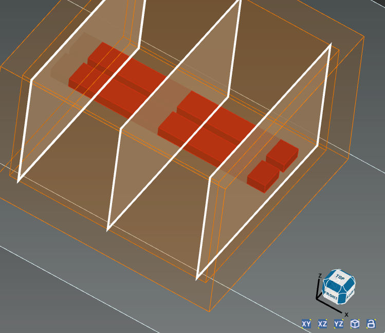
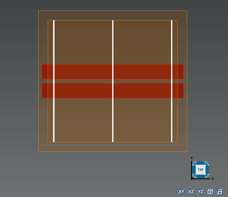
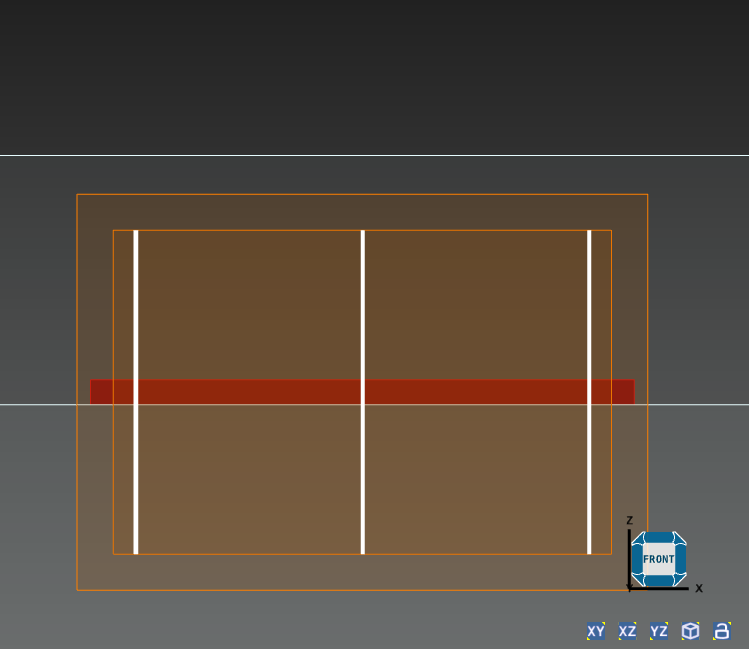
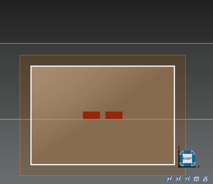
In the (simplified) example device below; Waveguides are in red. The ports (source and monitor) are the white rectangles, located at
x=0,1,2Propagating a mode from left to right;
The S parameter from the source to the middle monitor should give some phase; i.e.,
exp(i phi), which depends on distance between them.The S parameter from the source to the monitor on the right should give the square of the first phase; i.e.,
exp(i 2 phi), given that they are located atx=0,1,2.The S matrix from the S parameter sweep does not hold this relation, instead I randomly get a minus sign on these phase; e.g., something I get
exp(i phi)and-exp(i 2 phi)for these matrix elements. -
February 13, 2024 at 11:40 pm
Guilin Sun
Ansys EmployeeIf E,H exist the solver will not give -E and -H.
In FDTD, the phase is set to be from -pi to pi. It should not be random.
Do you pick up one value of the phase at the center of the mode? In general phase is space-distributive, and the phase will not be the same after mode propagates some distance cross a monitor plane. Once again the mode is not a plane wave so mode phase is not uniform in a plane.
Due to numerical errors, the phase will not be double from L1 to 2*L1. The monitor2 does not know the phase at monitor1. the phase is calculated by angle(imag(Em)/real(Em)) from the monitor data. Therefore the result from simulation will differ a little due to numerical error from S parameter propagation. The longer the propagation the larger the error of the phase.
May I know the purpose/goal to have two sets of output ports?
-
February 14, 2024 at 6:46 am
amitrotem2
Subscriberlet’s pause for a sec, can you tell me how to
copydcardof the modes in a port ? So I can useexpandon them?Now let’s continue;
When you say
E,His preferable by the solver you assume that they are positive in some sense? maybe that the integral overEis positive?Ecould be negative, so the solver will give-E?Ecould also be zero in the integral sense; e.g., for the anti-symmetric mode of the system.I’m not talking about the phase of the field at some point in space.
I’m talking about the phase of the scattering matrix elements, which only the sign (plus or minus) is “random”. Probably due to numerical erros somewhere else. The other numerical errors in that phase, due to propagation, are much much smaller.I used 2 output ports just for illustrative purposes. We can ignore the middle port, so the matrix element is somtimes
exp(i theta)and sometimes-exp(i theta). Which is still a problem If I want to compare between this S matrix to an S matrix of different device with slightly different design. -
February 14, 2024 at 4:34 pm
Guilin Sun
Ansys EmployeeCopydcard: https://optics.ansys.com/hc/en-us/articles/360034930233-copydcard-Script-command
When you say E and -E, I guess you are based on the actual sign of max E (Ex,Ey, or Ez). Right? Only one E component or H component can be zero, not the overall E-field, eg abd(E)=sqrt(Ex^2+Ey^2+Ez^2) (not here Ez means abs(Ex)).
The sign of S matrix is not random. It is Out=S*In https://optics.ansys.com/hc/en-us/articles/360042095873-Metamaterial-S-parameter-extraction
We cannot control the sign. If it has negative sign, it will be. Do you mean when you run simulation at different times the sign changes? if so, please check if the port mode is changed.
-
February 14, 2024 at 7:21 pm
amitrotem2
SubscriberCould you be more specific about the
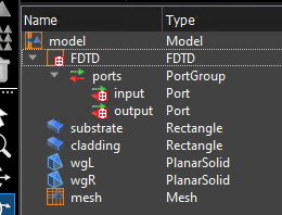
copydcardthing? I am familiar with the link you sent but still could not get the dcard - I attached my model structure.copydcard("::model::FDTD::ports::input::mode 1")fails.By
EI mean the the vectorE(x,y,z), so I meanE(x,y,z),H(x,y,z)and-E(x,y,z),-H(x,y,z).By zero (in the integral sense) I meant that the integral of
Eyis zero. Which is the dominent part of the mode.Anyway, yes, the sign of
real(Ey)in the port changes. This happens for example when I change the location of the port along the waveguide, which does not change along the x direction, so the port "sees" the same 2D slice, but gives the mode with a minus sign.This "randomness", or arbitrariness, affects the calculated S matrix. For
Out=S*In, if the modes that defineOutand/or the modes ofInchanges by a minus sign, the calculated S matrix shows that minus sign! Hence, the sign of the S matrix element is arbitrary.If I can project the basis of
Inonto the basis ofOutI would be able to get this sign, and correct for it. That is way I need tocopydcardthe ports and useexpandon them. -
February 14, 2024 at 9:37 pm
Guilin Sun
Ansys EmployeeFor the copydcard, sorry, you cannot specify which mode to be copied. It can only copye the fields in the monitor of the port. It is different in FDTD from FDE, where in FDE you can specify one mode whereas FDTD can only specify monitor.
”By
EI mean the the vectorE(x,y,z), so I meanE(x,y,z),H(x,y,z)and-E(x,y,z),-H(x,y,z).”The mode solver gives the mode profile by solving the eigen equations. We have no control the signs of the fields, and only one set is given in ports. Did you see that the simulation sometimes gives E(x,yz) and other times gives -E(x,y,z)?
I am confused by this.
”By zero (in the integral sense) I meant that the integral of
Eyis zero. Which is the dominent part of the mode.”I do not know the physical meaning of such average. The mode profile is distributive in nature. Although you can integrate the complex Ey, others can integrate abs(Ey), or abs(Ey)^2. It is all up to the author to determine which one to be used and its correspondent physics. We are here to help you doing the simulation. As the interpretation of the results I could not comment more.
Let’s forcus on the sign issue first.
-
February 15, 2024 at 7:50 am
amitrotem2
SubscriberYou mean I can only do
copydcard("::model::FDTD::ports::input")? to get the fields that the monitor sees during propagation? this also fails.
So how can I get the eigen modes from the port? and check the overlap between them?Yes, the signs of the modes used for mode expansion changes in the port. Depending on smilingly small things, like slight changes to the mesh.
I am not surprised by this. I just want obtain this sign.Check this super simple example that exhibit this sign arbitrariness;
?M1 = [0,1;1+eps0,0];
?M2 = [0,1;1-eps0,0]; # seemingly the same matrix as M1, up to numerical error
?In = eig(M1,2);
?Out = eig(M2,2); # the second eigenvector in M2 has a minus sign compared to M1
?S = mult(Out , inv(In)); # This "scattering" matrix is way off the identity matrix
I wasn't refering to any physical meaning for the average field. However, I was thinking about the average values of the 2nd eigen vector in the example above, which average to zero. I'm not sure if it's analogous. But in both cases we have small numerical changes that produce some minus sign, that affects the scattring matrix.
-
February 20, 2024 at 7:25 am
amitrotem2
SubscriberWhere do we stand with this?
-
-
February 20, 2024 at 5:29 pm
Guilin Sun
Ansys EmployeeIt seems copydcard does not work for port object.
you can use getresult :
EH2=getresult("::model::FDTD::ports::port 2","mode profiles");
to get E and H fields of the mode.
Please do not use eps0 as it is reserved for permittivity in vacuum.
This is unfortunate for the sign flip with small pertubation. Please try Matlab and see its result.
Let's resolve issues one by one with separate post.
-
February 22, 2024 at 9:28 am
amitrotem2
SubscriberCan I create a data card from the fields?
Or do I need to imulateexpandby takingcrossandintegratebetween the modes?Can we expect Lumerical will have this functionallity in the next release?
Thanks for noting the
eps0thing, I wasn't aware. Luckly for me the permittivity in SI units is small.
I not using Matlab. But I can say this also happens in Julia, if the matrix is complex. For real numbers it doesn't, because it's a different algorithm.For an actually complex matrix (e.g, [0,1i;1,0]) we can even get a phase change, not just a sign change.
These phases are not a bug, it's a choice of the algorithm. I think that for every choise like that, I can find a matrix that will have this phase "sensitivity". So I think it's reasonable ask to be able to easily obtain these sign flips, and correct for them.
-
February 22, 2024 at 9:36 am
amitrotem2
SubscriberYou can check this happens in FDE.
I’m running this on 2023 R2.3
Usually one of the mode in the loops have a minus relative to the others.Also, it seems that
findmodesresets the random number generator !
clc;
cleardcard;
closeall;
newproject;
## design
addrect;
set("y",0);set("y span",1e-6);
set("x",0);set("x span",1e-6);
set("z",0);set("z span",0.2e-6);
set("material", "Si (Silicon) - Palik");
## solver
addfde;
set("solver type", "2D X normal");
set("x",0);
set("y",0);set("y span",2e-6);
set("z",0);set("z span",1e-6);
set("number of trial modes", 4);
set("mesh cells z", 50);
set("mesh cells y", 50);
## get mode
K=10;
randreset(1);
for (k=1:K){
   findmodes; # same structure
   copydcard("mode2", "m"+num2str(k));
   switchtolayout;
   ?rand(); # why does findmodes reset the seed ??
}
## get neff and expand modes
neff_list = matrix(K);
Smat = matrix(K,K);
for (k=1:K){
   neff_list(k) = getdata("m"+num2str(k), "neff");
   for (j=1:K){
      X = expand("m"+num2str(k),"m"+num2str(j));
      Smat(j,k) = X(1); # should be 1
   }
}
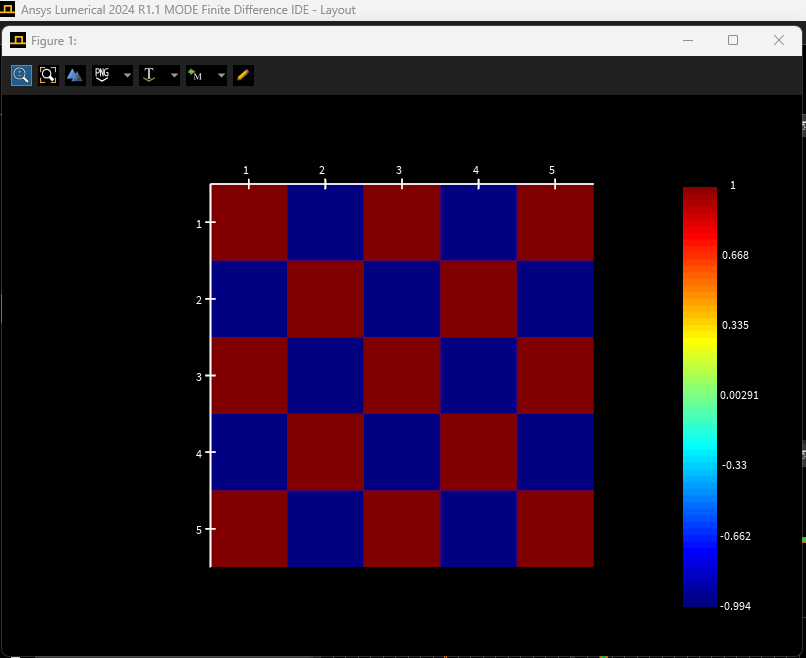
## neff is the same
?neff_list;
## modes have minus signs
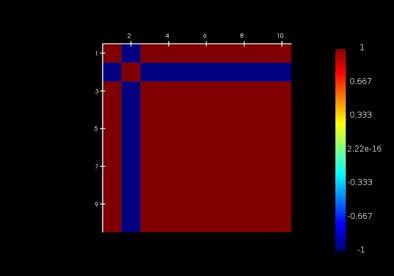
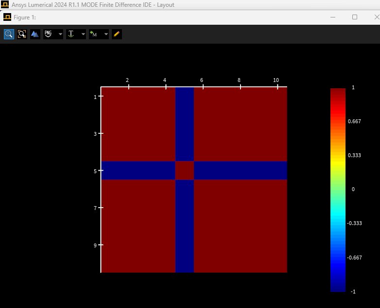
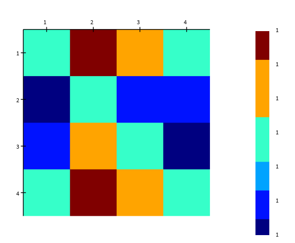
image(real(Smat)); -
February 22, 2024 at 5:05 pm
Guilin Sun
Ansys EmployeeYes, you are absolutely correct that the seed to find mode is random.
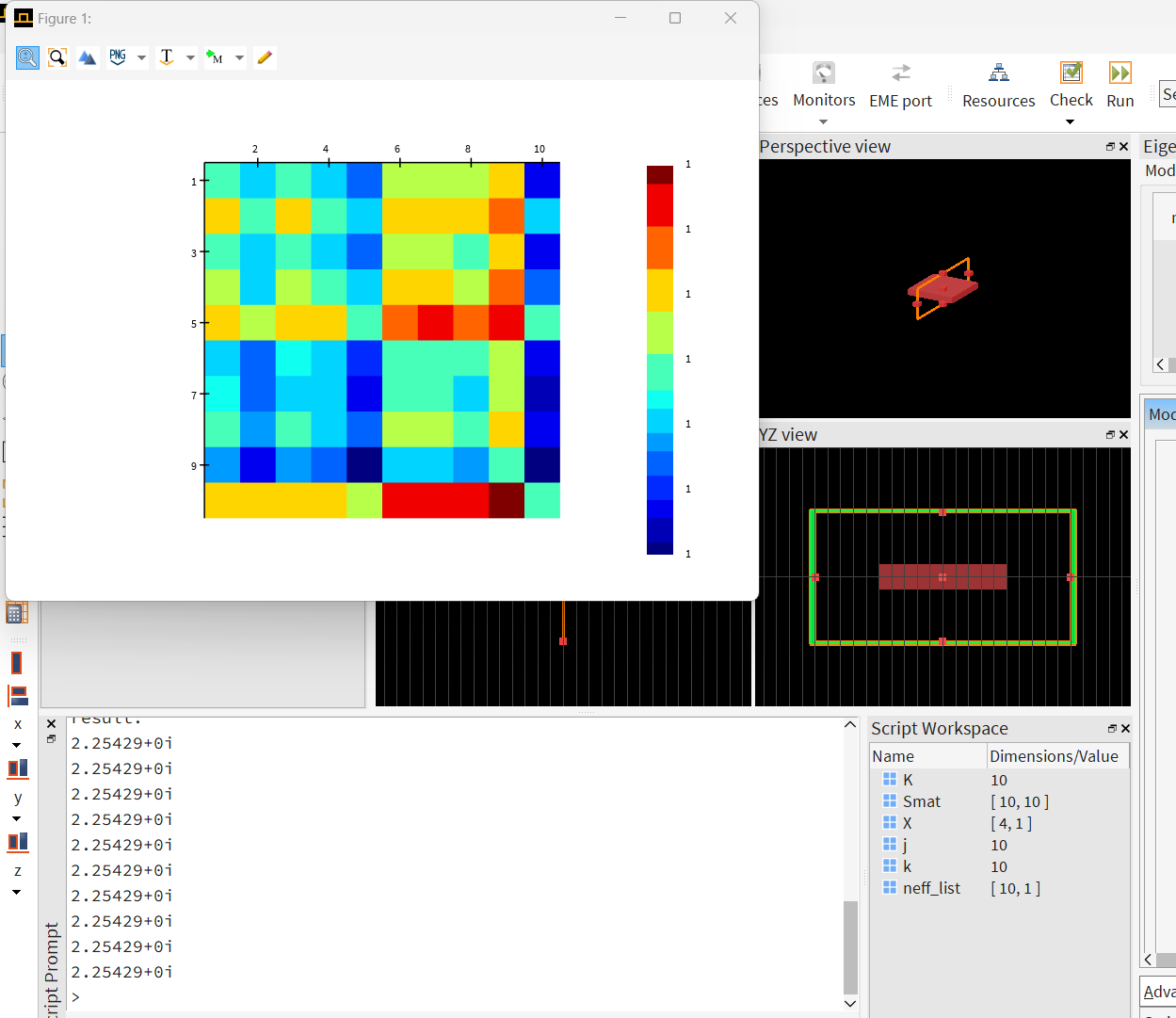
I tested your script and the result is as follows:
result:
0.449832
result:
0.449832
result:
0.449832
result:
0.449832
result:
0.449832
result:
0.449832
result:
0.449832
result:
0.449832
result:
0.449832
result:
0.449832
result:
2.25429+0i
2.25429+0i
2.25429+0i
2.25429+0i
2.25429+0i
2.25429+0i
2.25429+0i
2.25429+0i
2.25429+0i
2.25429+0iYou may need to download and install the latest version.
-
February 22, 2024 at 6:26 pm
-
-
February 22, 2024 at 5:09 pm
Guilin Sun
Ansys Employee"Can I create a data card from the fields?"
No.
"do I need to imulateexpandby takingcrossandintegratebetween the modes?"You can do this with script, once you get the mode fields.
"Can we expect Lumerical will have this functionallity in the next release?"
You can file a feature request.
"I not using Matlab. But I can say this also happens in Julia, if the matrix is complex. For real numbers it doesn't, because it's a different algorithm.For an actually complex matrix (e.g, [0,1i;1,0]) we can even get a phase change, not just a sign change.
These phases are not a bug, it's a choice of the algorithm. I think that for every choise like that, I can find a matrix that will have this phase "sensitivity". So I think it's reasonable ask to be able to easily obtain these sign flips, and correct for them."
I agree.
Sometimes it is really algorithm-dependent.
-
February 22, 2024 at 6:40 pm
-
February 23, 2024 at 3:36 pm
-
March 13, 2024 at 2:19 pm
-
March 13, 2024 at 4:37 pm
Guilin Sun
Ansys EmployeeUnfortunately the seeds for FDE are random and might be machine dependent. and the back propagation modes are also physical. I could not duplicate your result:
what OS version you are using?
You may try to disable the "rand", or reset it like this:
?randreset();
I do not see the necessity here using "rand".
I tested your script. with randreset as well as disabled "rand", they all give the same result on Win11:
We need to duplicate the issue if it is a bug.
-
March 14, 2024 at 9:20 am
amitrotem2
SubscriberI'm running on a Windows 11 Pro 23H2.
You can get somthing more reproducible by moving the rectangle (or the solver region) along the wide axis.
Here I moved the solver region so the coordinates of the mode won’t change.
clc;
cleardcard;
closeall;
newproject;
## design
addrect;
set("x",0);set("x span",1e-6);
set("y",0);set("y span",1e-6);
set("z",0);set("z span",0.2e-6);
set("material", "Si (Silicon) - Palik");
## solver
addfde;
set("solver type", "2D X normal");
set("x",0);
set("y",0);set("y span",2e-6);
set("z",0);set("z span",1e-6);
set("number of trial modes", 3);
set("mesh cells z", 50);
set("mesh cells y", 50);
## get mode
K = 5;
for (k=0:K){
    setnamed("FDE", "y", (k/K-0.5)*0.5e-6);
    #setnamed("rectangle", "y", (k/K-0.5)*0.5e-6);
    findmodes;
    copydcard("mode2", "m"+num2str(k));
    switchtolayout;
}
## get neff and expand modes
neff_list = matrix(K);
Smat = matrix(K,K);
for (k=1:K){
    neff_list(k) = getdata("m"+num2str(k), "neff");
    for (j=1:K){
        X = expand("m"+num2str(k),"m"+num2str(j));
        Smat(j,k) = X(1); # should be 1
    }
}
## modes have minus signs
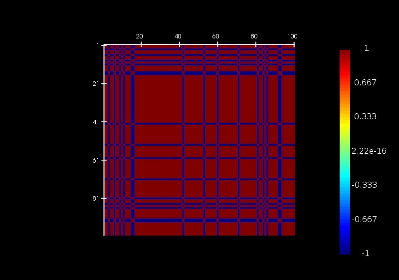
image(real(Smat)); -
March 14, 2024 at 10:00 pm
Guilin Sun
Ansys EmployeeI can duplicate your result now. However it is the 2nd mode. The fundamental mode works fine.
I believe it is due to the global deck issue, not the findmodes. The problem is, once the data is in the global deck, we cannot access it except directly use its data. That said, we cannot check what happens to the global deck data.
If you can save the mode data in script, and then calculate the "expand" with sweep, and if it gives the same wrong result, then it is the findmodes issue.
Please note that the global deck data is not designed to use this way. If your goal is to prove that the gobal deck has something wrong with such usage, I agree. However it may not be get rectified, as all the bugs and features are by vote to correct, and it takes time.
In order not to hinder your project, I would strongly suggest that you use script to calculate the expansion,since the formula is known.
-
March 21, 2024 at 4:44 am
amitrotem2
SubscriberHere is an example with s-parameter sweep in FDTD.
##
clc;
cleardcard;
closeall;
newproject;
## design
x_shift = 100e-9; # length of blocks
y_shift = 1e-9; # offset for the first and last blocks
K = 3;
for (k=0:K){
    addrect; set("name", "rect"+num2str(k));
    set("x",k*x_shift);
}
selectpartial("rect");
set("x span",x_shift);
set("y",0);set("y span",1e-6);
set("z",0);set("z span",0.2e-6);
set("material", "Si (Silicon) - Palik");
### off set the first and last blocks
setnamed("rect0", "y", -y_shift);
setnamed("rect"+num2str(K), "y",  y_shift);
## solver
addfdtd;
set("x min",-x_shift/2);set("x max",(K+0.5)*x_shift);
set("y",0);set("y span",K*y_shift+2e-6);
set("z",0);set("z span",1e-6);
set("mesh accuracy", 4);
setresource("FDTD", "GPU", true);
setnamed("FDTD", "express mode", true);
## ports in the middle of each block
for (k=0:K){
    addport();
    set("x", k*x_shift);
    if (1.5 < k){set("direction", "Backward");}
}
selectpartial("FDTD::ports::port");
set("auto update", false);
set("frequency dependent profile", false);
set("mode selection", "user select");
set("selected mode numbers", 2); # 2nd mode is antisymmetric and will show the issue
clearportmodedata;
seteigensolver("correct backward propagating modes", false);
seteigensolver("correct backward propagating modes when pml is present", false);

wavelength = 1560e-9;
setglobalsource("set frequency", true);
setglobalsource("center wavelength", wavelength);
setglobalsource("wavelength span", 0);
setglobalmonitor("wavelength center", wavelength);
setglobalmonitor("frequency points", 1);
setglobalmonitor("wavelength span", 0);
setglobalmonitor("use source limits", 1);
##
save("sign_arb.fsp");

## s-parameter sweep
addsweep(3);
runsweep;
sweepdata = getsweepresult("s-parameter sweep","S matrix");
Smat = pinch(sweepdata.S); # scattering matrix

### see the issue when propagating from port 3 to 4 vs from
?conj(Smat(3,1))*Smat(4,1); # excite port 1, and look at the propagating from port 3 to 4
?conj(Smat(3,2))*Smat(4,2); # excite port 2, and look at the propagating from port 3 to 4
?conj(Smat(2,4))*Smat(1,4); # excite port 4, and look at the propagating from port 2 to 1
?conj(Smat(2,3))*Smat(1,3); # excite port 3, and look at the propagating from port 2 to 1

##
neff_list = matrix(K+1);
S0 = matrix(K+1,K+1);
for (k=1:K+1){
    NEFF = getresult("FDTD::ports::port "+num2str(k), "neff");
    neff_list(k) = NEFF.neff;
    mode1 = getresult("FDTD::ports::port "+num2str(k), "mode profiles");
    for (j=1:K+1){
        mode2 = getresult("FDTD::ports::port "+num2str(j), "mode profiles");
        cr12 = pinch(cross(mode1.E2, mode2.H2));
        cr11 = pinch(cross(mode1.E2, mode1.H2));
        cr22 = pinch(cross(mode2.E2, mode2.H2));
        cr12 = integrate(pinch(cr12(:,:,1)), [1,2], pinch(mode1.y), pinch(mode1.z));
        cr11 = integrate(pinch(cr11(:,:,1)), [1,2], pinch(mode1.y), pinch(mode1.z));
        cr22 = integrate(pinch(cr22(:,:,1)), [1,2], pinch(mode1.y), pinch(mode1.z));
        S0(j,k) = cr12/sqrt(cr11*cr22);
    }
}
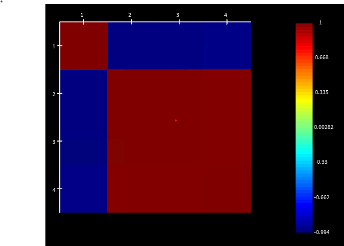
## modes have minus signs
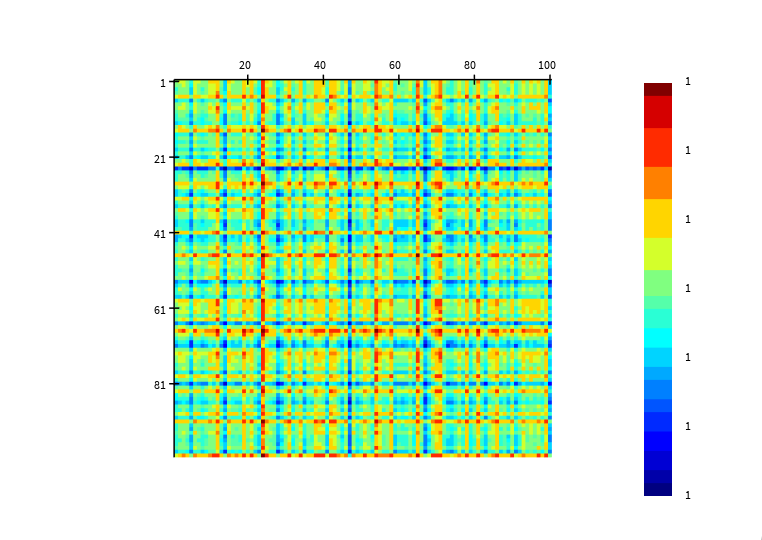
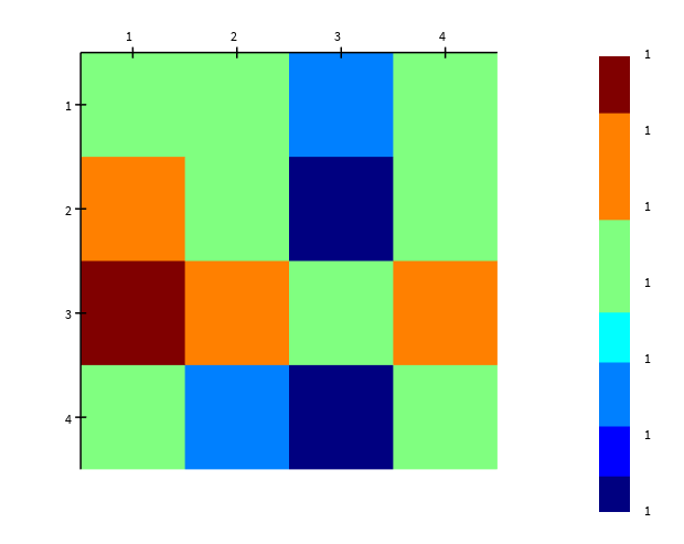
image(real(S0)); -
March 21, 2024 at 8:51 pm
Guilin Sun
Ansys EmployeeThank you for your time to delibrately duplicate the issue. Hoever if I modified the script I got correct result as you expected (please note that I did not modify other part of the scrip file):
clc;
cleardcard;
closeall;
newproject;
## design
x_shift = 300e-9; # length of blocks
y_shift = 1e-9; # offset for the first and last blocks
K = 3;
#for (k=0:K){
#addrect; set("name", "rect"+num2str(k));
#set("x",k*x_shift);
#}
#selectpartial("rect");
#set("x span",x_shift);
#set("y",0);set("y span",1e-6);
#set("z",0);set("z span",0.2e-6);
addrect;
set("x",0);set("x span",9e-6);
set("material", "Si (Silicon) - Palik");
### off set the first and last blocks
#setnamed("rect0", "y", -y_shift);
#setnamed("rect"+num2str(K), "y", y_shift);
## solver
addfdtd;
set("x min",-x_shift/2);set("x max",(K+0.5)*x_shift);
set("y",0);set("y span",K*y_shift+2e-6);
set("z",0);set("z span",1e-6);
set("mesh accuracy", 4);
setresource("FDTD", "GPU", true);
setnamed("FDTD", "express mode", true);
## ports in the middle of each block
for (k=0:K){
addport();
set("x", k*x_shift);}
# if (1.5}
selectpartial("FDTD::ports::port");
set("auto update", false);
set("frequency dependent profile", false);
set("mode selection", "user select");
set("selected mode numbers", 2); # 2nd mode is antisymmetric and will show the issue
clearportmodedata;
seteigensolver("correct backward propagating modes", false);
seteigensolver("correct backward propagating modes when pml is present", false);
wavelength = 1560e-9;
setglobalsource("set frequency", true);
setglobalsource("center wavelength", wavelength);
setglobalsource("wavelength span", 0);
setglobalmonitor("wavelength center", wavelength);
setglobalmonitor("frequency points", 1);
setglobalmonitor("wavelength span", 0);
setglobalmonitor("use source limits", 1);
##
save("sign_arb.fsp");
## s-parameter sweep
addsweep(3);
runsweep;
sweepdata = getsweepresult("s-parameter sweep","S matrix");
Smat = pinch(sweepdata.S); # scattering matrix
### see the issue when propagating from port 3 to 4 vs from
?conj(Smat(3,1))*Smat(4,1); # excite port 1, and look at the propagating from port 3 to 4
?conj(Smat(3,2))*Smat(4,2); # excite port 2, and look at the propagating from port 3 to 4
?conj(Smat(2,4))*Smat(1,4); # excite port 4, and look at the propagating from port 2 to 1
?conj(Smat(2,3))*Smat(1,3); # excite port 3, and look at the propagating from port 2 to 1
##
neff_list = matrix(K+1);
S0 = matrix(K+1,K+1);
for (k=1:K+1){
NEFF = getresult("FDTD::ports::port "+num2str(k), "neff");
neff_list(k) = NEFF.neff;
mode1 = getresult("FDTD::ports::port "+num2str(k), "mode profiles");
for (j=1:K+1){
mode2 = getresult("FDTD::ports::port "+num2str(j), "mode profiles");
cr12 = pinch(cross(mode1.E2, mode2.H2));
cr11 = pinch(cross(mode1.E2, mode1.H2));
cr22 = pinch(cross(mode2.E2, mode2.H2));
cr12 = integrate(pinch(cr12(:,:,1)), [1,2], pinch(mode1.y), pinch(mode1.z));
cr11 = integrate(pinch(cr11(:,:,1)), [1,2], pinch(mode1.y), pinch(mode1.z));
cr22 = integrate(pinch(cr22(:,:,1)), [1,2], pinch(mode1.y), pinch(mode1.z));
S0(j,k) = cr12/sqrt(cr11*cr22);
}
}
## modes have minus signs
image(real(S0));
You may need to check why abs(S) is so small.
?(Smat);
result:
0.000255494+0.0044802i 0.000224482+0.000458643i -0.000214006-0.00040015i -0.0151803-0.00966112i
0.000173741+0.000277187i -0.000229734-0.000190805i 0.00035439+0.000313608i 0.0174794+0.00431687i
-0.000239793-0.000210712i 0.000312866+0.000129124i -0.000306754-9.57862e-06i -0.0179214+0.00155494i
-0.00388469+0.00246871i 0.00286938-0.00359021i -0.00153308+0.00433298i 5.43626e-05-0.0045861i -
March 22, 2024 at 5:15 am
amitrotem2
SubscriberFrom what I see you completely changed the design.
I had 4 blocks along X, with offset in Y. And a port on each block. My Smatrix had 8 values close to 1, and 8 small values. I only care about the phase of the larger values.
-
March 22, 2024 at 4:05 pm
Guilin Sun
Ansys EmployeeYes, I modified, since the minor shifts may cause some issues.
To check the consistency and isolate the issues, a straight waveguide is preferred. The phase is very sensitive to small values, since it is calculated from angle(imag(S)/real(S)). if the imag or the real part is small, due to numberical errors, it can flip the sign of the value. Thus the phase can be quite different. This is not uncommon for phase calculation.
-
March 22, 2024 at 6:10 pm
amitrotem2
SubscriberI think you get small values because you moved the ports away from the blocks, or didn't flip their direction.
The original code show sign flips on S matrix values the has magnitude close to 1
The small shifts in Y are a sure way to see the issue of the sign flip. You can also see these with larger Y shifts.
-
March 22, 2024 at 6:53 pm
Guilin Sun
Ansys EmployeeHere is the result I got directly from your script (except line 34 is modified):
?abs(Smat);
result:
0.000439021 0.0166555 0.017211 0.000397579
0.0028741 0.00273113 0.017198 0.000322681
0.00300699 0.00305221 0.00322448 0.000252065
0.000378088 0.00033553 0.000237014 0.000287072After the straight waveguide is added, I use the following script:
## solver
addfdtd;
set("x min",-x_shift/2);set("x max",(K+0.5)*x_shift);
set("y",0);set("y span",K*y_shift+2e-6);
set("z",0);set("z span",1e-6);
set("mesh accuracy", 4);
setresource("FDTD", "GPU", true);
setnamed("FDTD", "express mode", true);
## ports in the middle of each block
for (k=0:K){
addport();
set("x", k*x_shift);
}
selectpartial("FDTD::ports::port");
set("auto update", false);
set("frequency dependent profile", false);
set("mode selection", "user select");
set("selected mode numbers", 2); # 2nd mode is antisymmetric and will show the issue
clearportmodedata;
seteigensolver("correct backward propagating modes", false);
seteigensolver("correct backward propagating modes when pml is present", false);
wavelength = 1560e-9;
setglobalsource("set frequency", true);
setglobalsource("center wavelength", wavelength);
setglobalsource("wavelength span", 0);
setglobalmonitor("wavelength center", wavelength);
setglobalmonitor("frequency points", 1);
setglobalmonitor("wavelength span", 0);
setglobalmonitor("use source limits", 1);
##
save("sign_arb.fsp");
## s-parameter sweep
addsweep(3);
runsweep;
sweepdata = getsweepresult("s-parameter sweep","S matrix");
Smat = pinch(sweepdata.S); # scattering matrix
### see the issue when propagating from port 3 to 4 vs from
?conj(Smat(3,1))*Smat(4,1); # excite port 1, and look at the propagating from port 3 to 4
?conj(Smat(3,2))*Smat(4,2); # excite port 2, and look at the propagating from port 3 to 4
?conj(Smat(2,4))*Smat(1,4); # excite port 4, and look at the propagating from port 2 to 1
?conj(Smat(2,3))*Smat(1,3); # excite port 3, and look at the propagating from port 2 to 1
##
neff_list = matrix(K+1);
S0 = matrix(K+1,K+1);
for (k=1:K+1){
NEFF = getresult("FDTD::ports::port "+num2str(k), "neff");
neff_list(k) = NEFF.neff;
mode1 = getresult("FDTD::ports::port "+num2str(k), "mode profiles");
for (j=1:K+1){
mode2 = getresult("FDTD::ports::port "+num2str(j), "mode profiles");
cr12 = pinch(cross(mode1.E2, mode2.H2));
cr11 = pinch(cross(mode1.E2, mode1.H2));
cr22 = pinch(cross(mode2.E2, mode2.H2));
cr12 = integrate(pinch(cr12(:,:,1)), [1,2], pinch(mode1.y), pinch(mode1.z));
cr11 = integrate(pinch(cr11(:,:,1)), [1,2], pinch(mode1.y), pinch(mode1.z));
cr22 = integrate(pinch(cr22(:,:,1)), [1,2], pinch(mode1.y), pinch(mode1.z));
S0(j,k) = cr12/sqrt(cr11*cr22);
}
}
## modes have minus signs
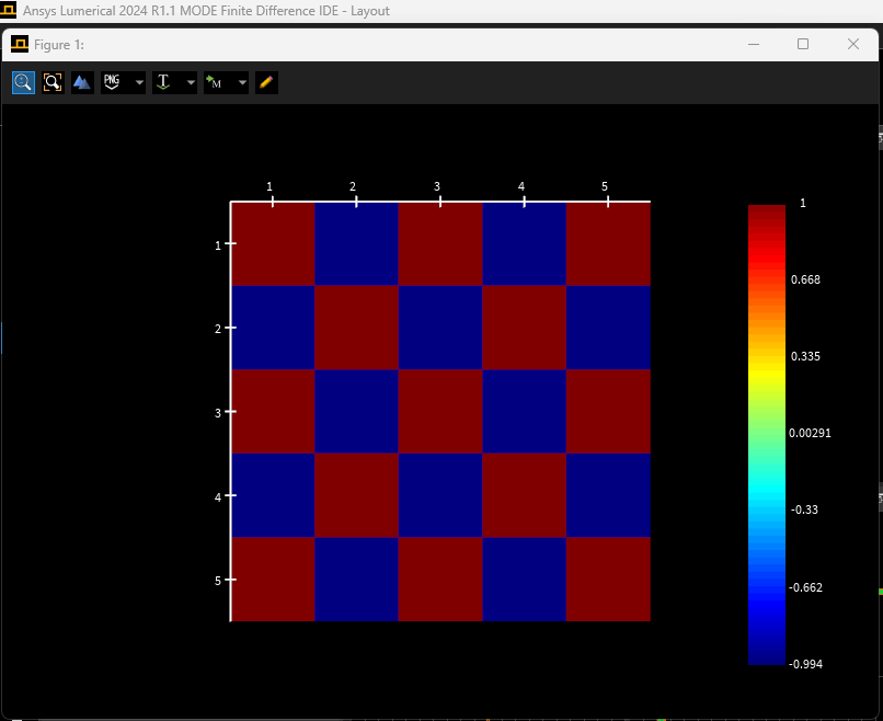
image(real(S0));
I got the result:
Please use ONE staright waveguide for testing.
-
March 22, 2024 at 8:43 pm
amitrotem2
SubscriberYou mean this;
set("direction", "Backward")
Why would you disable that ? If you leave it as is you get values close to 1?abs(Smat);
result:
0.00548752 0.0184426 0.99328 0.977123
0.00729792 0.0060976 0.999832 0.9935
0.99337 0.99988 0.000633771 0.000932185
0.977351 0.9933 0.00385249 0.00270568The whole point is to have some shift along the Y direction like in Bragg grating. Are you worried about the intersection areas? you can add a narrow block along the other block, still get the same result. Even if y_shift is 20 nm, you still get the minus signs.
-
-
March 22, 2024 at 8:50 pm
-
March 22, 2024 at 8:51 pm
Guilin Sun
Ansys EmployeeI did not change this line
set(“direction”, “Backward”)
Actually your file sent previously did not have this line. which object is this for?
-
March 22, 2024 at 9:53 pm
amitrotem2
SubscriberSorry, the chat does somthing to '<' followed by 'k' sign and showed only this 'if (1.5}'
Is that what you commented out?
I reverse the direction of ports 3 and 4.for (k=0:K){
addport();
set(“x”, k*x_shift);
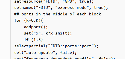
if (1.5 < k){set(“direction”, “Backward”);}
} -
March 25, 2024 at 11:29 pm
Guilin Sun
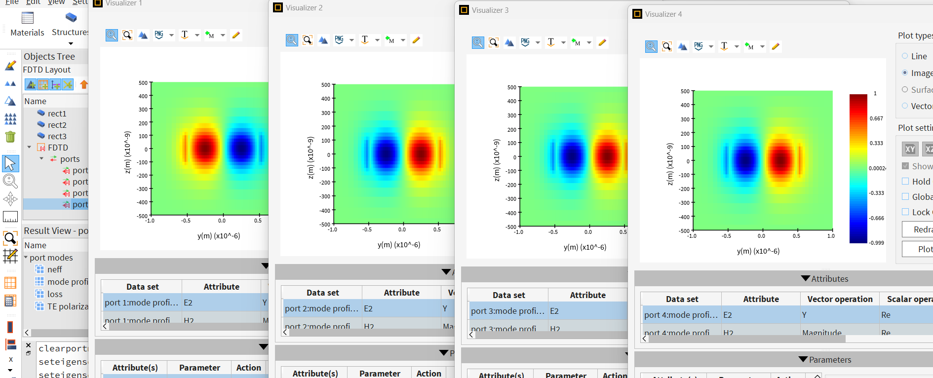
Ansys EmployeeI think the root cause of this is: some modes flips signs:
My tests show that in the following two cases the port modes are the same:
1: the ports do not shift;
2: using one waveguide
Why they change is hard say, as mentioned previously, we cannot control the didrection of mode direction.
I would like to check the actual device, and suggest that you manually check if the modes are the same.
-
March 30, 2024 at 6:48 pm
amitrotem2
SubscriberYES !! the mode change sign !
Changing direction is another issue.
I Think this analysis needs to be included as a basic analysis in Lumerical. When can I expect that?
And, just to remind you, I see these sign changes even if I don't shift the blocks and/or use a single waveguide.
-
April 1, 2024 at 3:16 pm
Guilin Sun
Ansys EmployeeSince seed searching the mode is random, it is hard to control.
You may file a feature request to control the modes: ix.lumerical.com
-
April 1, 2024 at 6:29 pm
amitrotem2
SubscriberI will.
But I think this bug should be fixed as soon as possible, and not go via feature request process.
-
- The topic ‘Arbitrary sign for eigen mode’ is closed to new replies.


-
4492
-
1494
-
1376
-
1209
-
1021

© 2025 Copyright ANSYS, Inc. All rights reserved.

