-
-
February 2, 2024 at 6:16 am
-
February 6, 2024 at 1:52 pm
Ivonne Marti
Ansys EmployeeHi Karen,
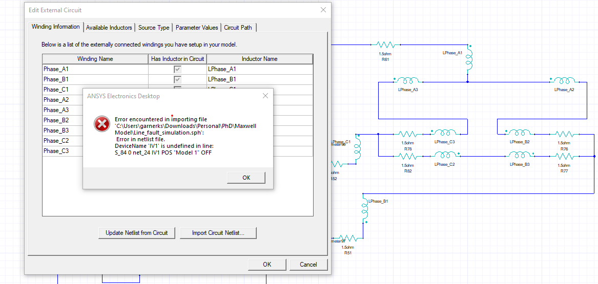
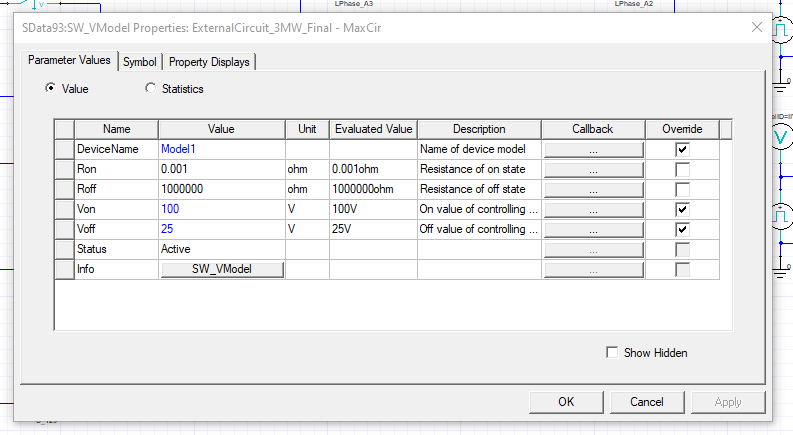
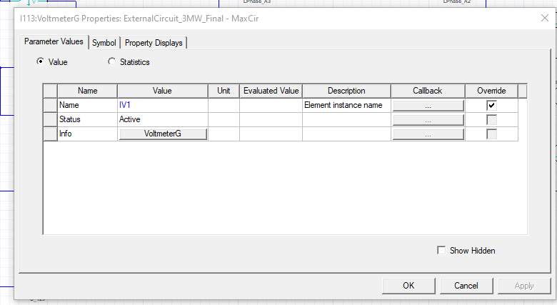
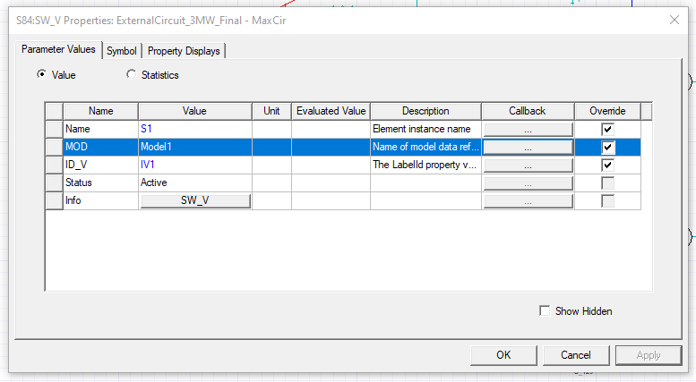
The error is pointing to the Voltmeter IV1 and the switch control Model1, looks like one is Positive and the other is OFF.
Please carefully check the setup of these components. I would suggest checking the characteristics of each one, to do this in the Properties window of each component you can find a direct link to Help.
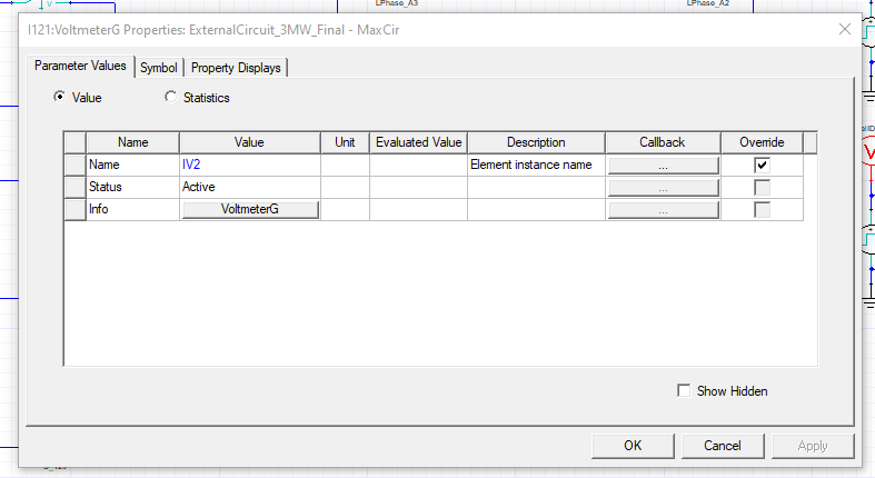
Note: check also the component IV2 because probably you have the same setting mistake.
Ivonne
-
February 7, 2024 at 3:07 pm
-
Viewing 2 reply threads
- The topic ‘Simulating line faults in Ansys Maxwell’ is closed to new replies.
Ansys Innovation Space
Trending discussions
- HFSS Incident Plane Wave excitement mode
- Ansys Maxwell 3D – eddy current
- Simulation of capacitor combining eddy currents with displacement currents
- dq graph non-conformity
- Simplorer+Maxwell Cosimulation results and Maxwell results mismatch
- Parametrizing coil “terminals” with coil geometry
- Maxwell circuit – PWM
- Plotting Ex, Ey and Ez in vector forms individually
- Ansys-MATLAB Co-Simulation
- Calculating E-field tangential to a 2D resonant structure on a sapphire chip
Top Contributors
-
1937
-
839
-
599
-
591
-
366
Top Rated Tags
© 2025 Copyright ANSYS, Inc. All rights reserved.
Ansys does not support the usage of unauthorized Ansys software. Please visit www.ansys.com to obtain an official distribution.