TAGGED: charge
-
-
January 29, 2024 at 8:32 am
handon
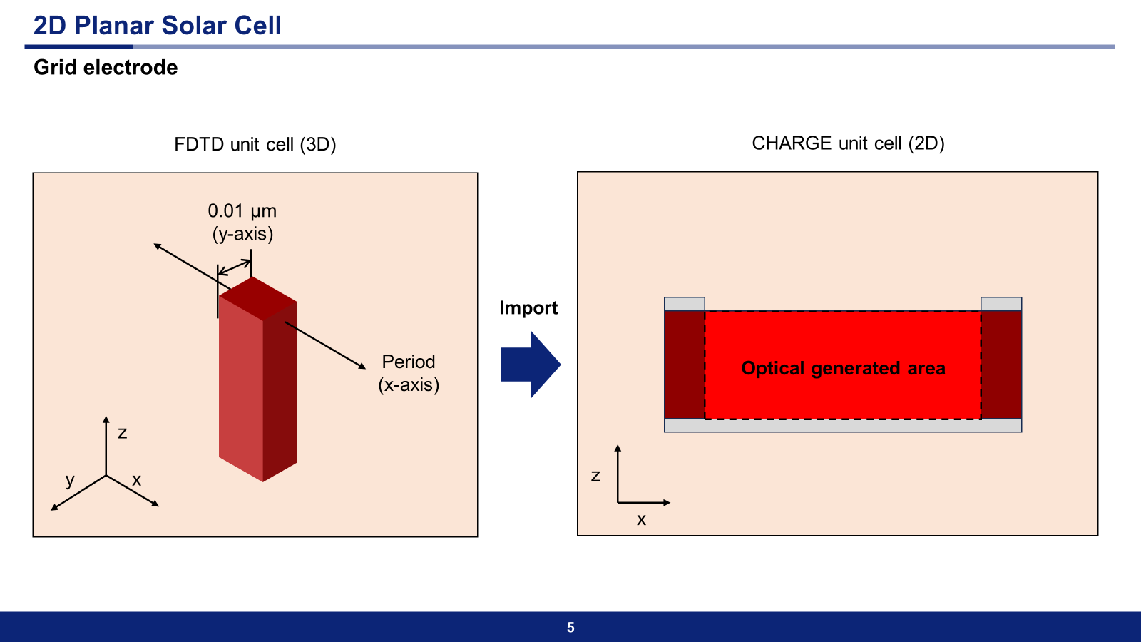
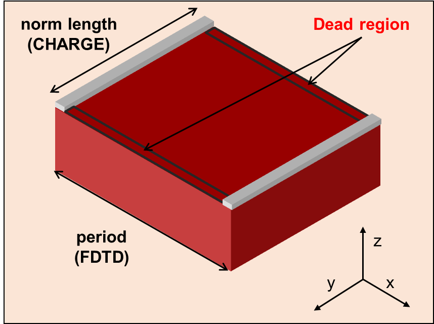
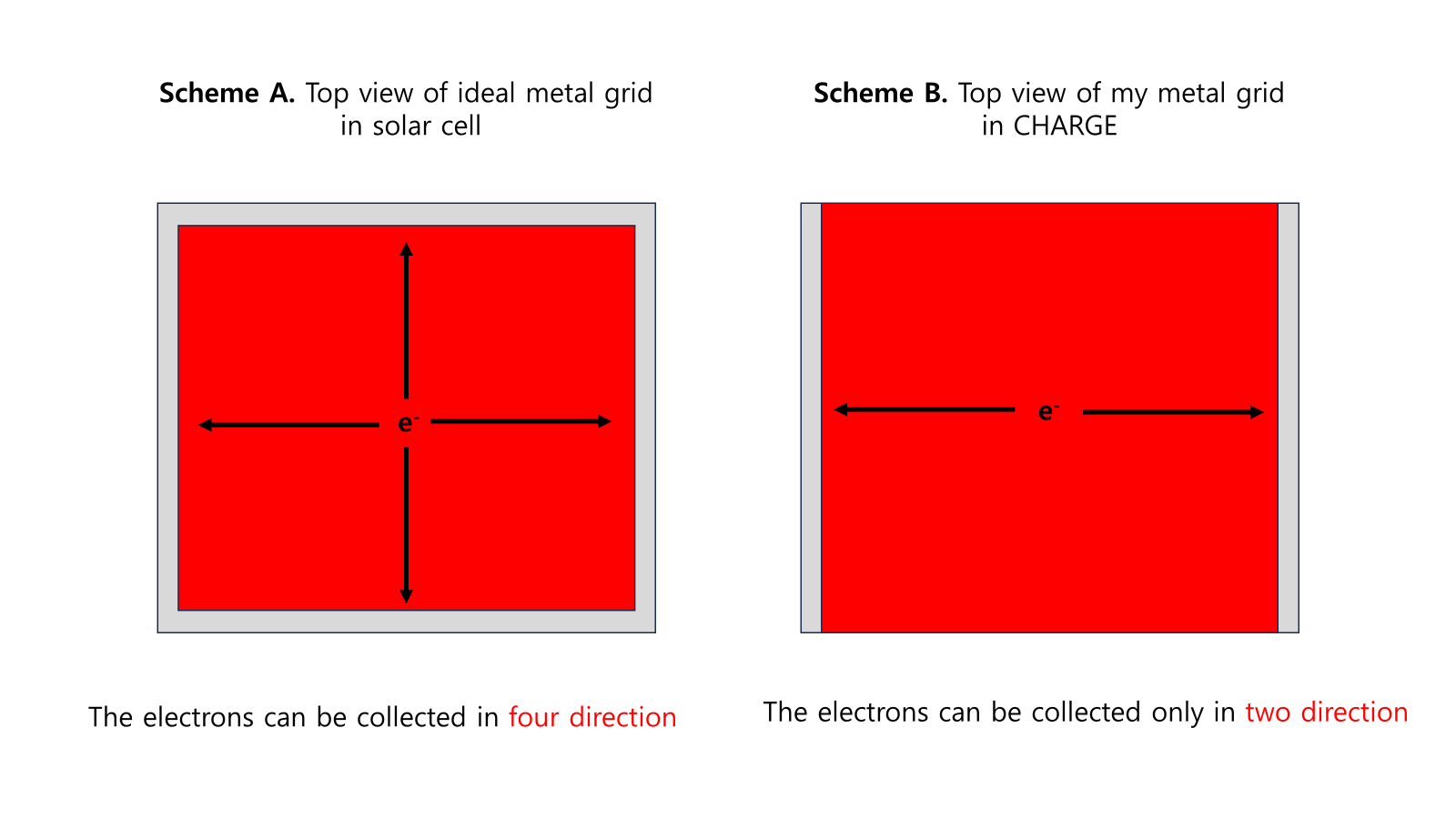
SubscriberHello, I have a question on simulating microgrid solar cell for photovoltaic performance (ex. Jsc, Voc, etc.)I questioned a similar topic before. But I think it is more related to CHARGE than FDTD so I start a new post.Here’s the link to my previous post:In my question, the microgrid solar cell represents a planar silicon solar cell that has a grid metal electrode and the spacing of the grid is micro-scale (max 500 μm).My final goal is to get the photovoltaic performance of the microgrid solar cell.It is not difficult to calculate optical generation rate of 500 μm microgrid solar cells. Using the feature ‘periods’ in the analysis group, I can obtain the optical generation rate, which is very long on the x-axis (500 μm) but narrow on the y-axis (0.01 μm).Then, this optical generation rate file is imported to CHARGE. In the CHARGE, I set the dimension of CHARGE simulation region to 2D Y-Normal and it makes the width of y from 0.001 μm to 500 μm by using the feature ‘norm length’.Originally, the memory requirements of this microgrid solar cell simulation are approximately 30,000 GB even though the mesh accuracy is 1.. But, the memory requirements can be significantly reduced with ‘period’ in FDTD and ‘norm length’ in CHARGE.However, the point of this simulation is the collection of carriers into the microgrid electrode and the analysis of the electrical properties of the solar cells. If I use the ‘norm length’ in the CHARGE, I can’t set the electrode in the x-axis because it is 2D-Y Normal. Microgrid solar cell in the 2D-Y Normal has only a parallel metal grid and the carrier is collected only 2-ways (in the x-axis).How can I design the metal grid solar cells that collect carriers in four ways? If I set the dimension of the CHARGE simulation to 3D, optical generation data should also be based on the 3D.And, as I said previously, it requires 30,000 GB of memory to run the FDTD simulation even though the mesh accuracy is 1.I don’t know all the features of CHARGE and lumerical script, so I guess the solution can be from CHARGE that I didn't know. -
January 30, 2024 at 2:40 pm
Afroditi Petropoulou
Ansys EmployeeDear Handon,
Thank you for reaching out to us!
I am not sure what is exactly your question.
If your structure has electrodes in all four sides of the microcell as shown in the top view of Scheme A, you will need to run a 3D simulation in both FDTD and CHARGE. 2D simulations suppose that the geometry in the normal direction is infinitely uniform.
For the FDTD part, since your structure is periodic, you could also try to use the RCWA solver which in most cases is faster and less time and resources consuming than FDTD.
Is your question whether you can run a 2D simulation in FDTD and then use the results in a 3D CHARGE simulation?
If yes, can you tell me which is exactly the 2D structure that you simulate in FDTD and what monitors and source you are using? Maybe some screenshots could also help.
Best regards,
Afroditi
-
- The topic ‘Mimic microgrid planar solar cells and analyze their electrial properties’ is closed to new replies.


-
4838
-
1587
-
1386
-
1242
-
1021

© 2026 Copyright ANSYS, Inc. All rights reserved.


