-
-
January 24, 2024 at 10:45 am
Jordi Lopez Leyva
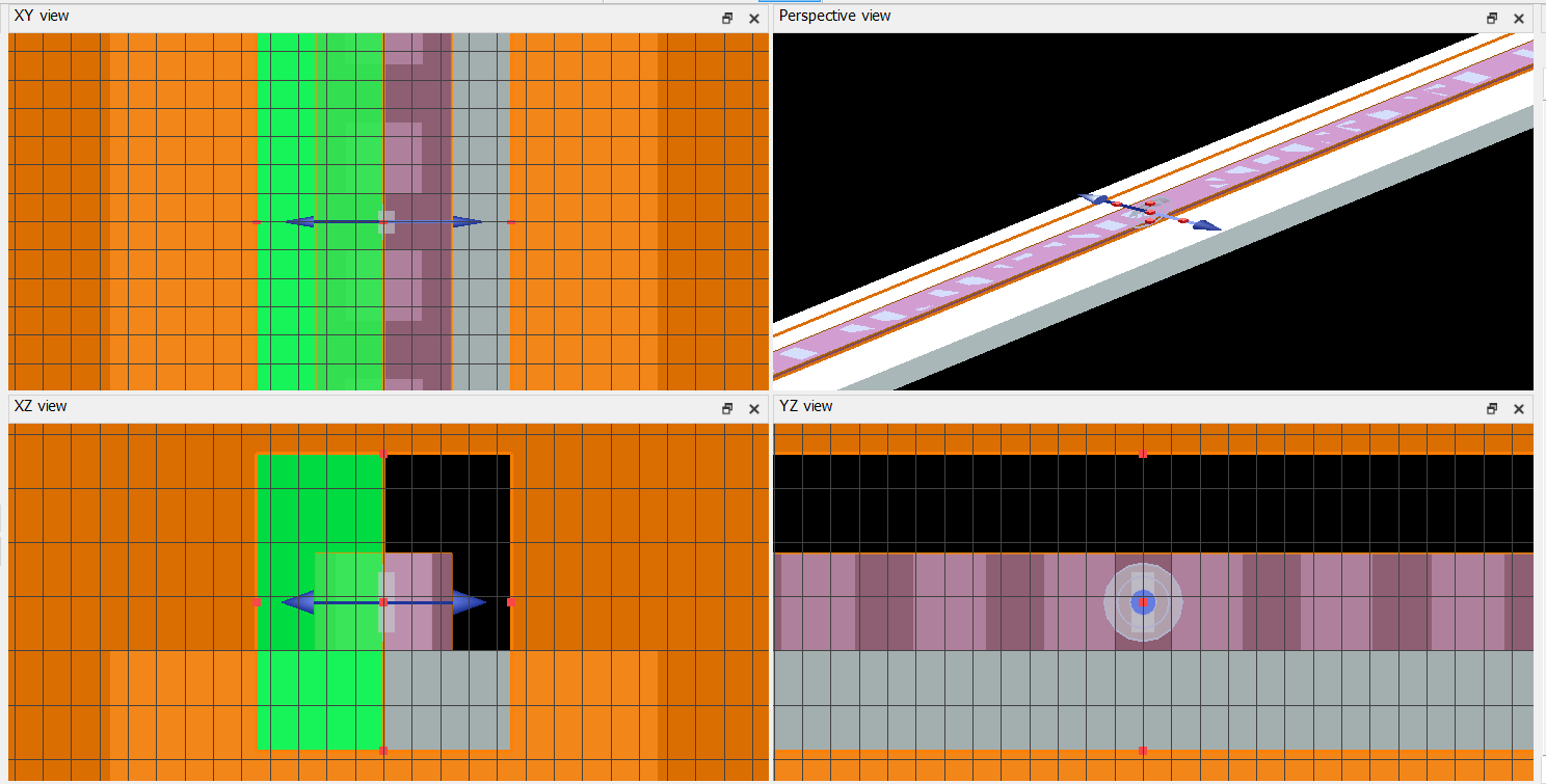
SubscriberI want to calculate the dipole power injected into a Photonic Crystal Nanobeam at the center in FDTD. However, the photonic crystal will have self reflectance. The Lumerical guide ("Understanding dipoles in non-homogeneous materials") only addresses metal boundaries and suggests using mirror sources, but in my case, I'm not sure if this applies. So how can I calculate the dipolepower in a selfreflecting structure such as a photonic crystal?
model:
-
January 24, 2024 at 7:28 pm
Amrita Pati
Ansys EmployeeHi Jordi,
I don't see any issue with the use of dipolepower script command. The normalization issue arises with sourcepower script command, so, it should only be used when the dipole is in a homogenous material. Is the material that the dipole suspended in dispersive?
Regards,
Amrita-
January 24, 2024 at 7:37 pm
Jordi Lopez Leyva
SubscriberHi Amrita,
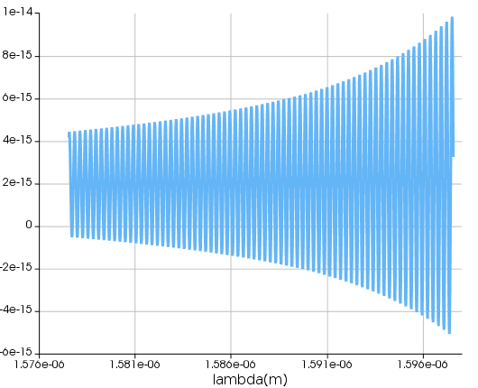
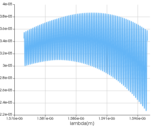
Thank you for the reply. In that case I have a related question. I'm currently doing simulation times of 30ps, stabilized boundary 30PML layers. However, when I use a narrow wavelength spacing (e.g less than 10nm), or I add a custom (n,k) import, I get oscillations in my dipolepower and transmission. My thought is that since the dipolepower monitor is placed at the center, the oscillations could be caused by reflections, or PML relfections. Additionally, I also see these oscillations in the transmission outside the photonic crystal. What could be causing those oscillations in power?
Example below is for custom (n,k) import
Dipolepower:
Transmission:
-
-
January 24, 2024 at 7:44 pm
Amrita Pati
Ansys EmployeeHi Jordi,
Is the material in which the dipole is situated, dispersive and or lossy?
Regards,
Amrita-
January 24, 2024 at 7:47 pm
Jordi Lopez Leyva
SubscriberHi Amrita,
No, I'm using GaAs - Palik. k index = 0.
Kindest regards,
Jordi Lopez Leyva
-
-
January 24, 2024 at 8:01 pm
Amrita Pati
Ansys EmployeeHi Jordi,
I would be interested to know how the dipolepower result compares to the power calculated from a transmission box. You can use a transmission box of width around 5 mesh cells in each direction around the dipole source. I believe the comparison could be useful for narrowing down on the cause.
Regards,
Amrita-
January 26, 2024 at 4:10 pm
Jordi Lopez Leyva
SubscriberHi Amrita,
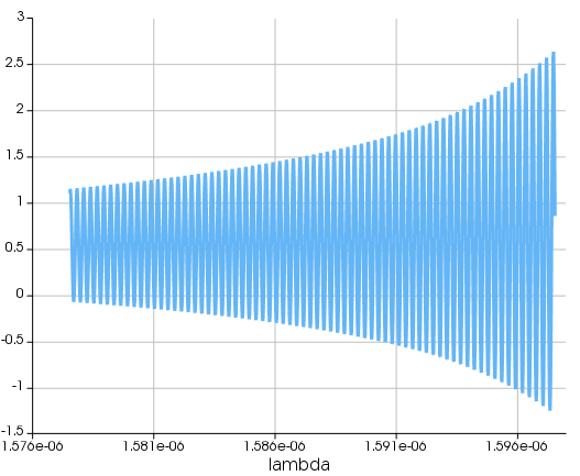
Here's the transmission box. It looks the same as the one from dipolepower (and the transmission box I have placed arroud the entire photonic crystal instead of only arround the source).
An additional note which could be important, I remember in a simulation where I used standard boundary condition with 8 PML layer, my simulations diverged, which I think could've been due to PML reflections (in movie I saw fields appearing after a long time as leakage probably from the PML). Could this be playing a role since my simulation region is narrow and/or my absorption in PML is not high enough (value same as stabilized)?
-
-
- The topic ‘How to calculate dipole power if structure self-reflecting’ is closed to new replies.


-
4858
-
1587
-
1386
-
1242
-
1021

© 2026 Copyright ANSYS, Inc. All rights reserved.


