-
-
January 17, 2024 at 7:55 am
K. H.
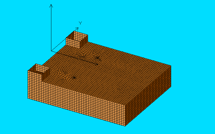
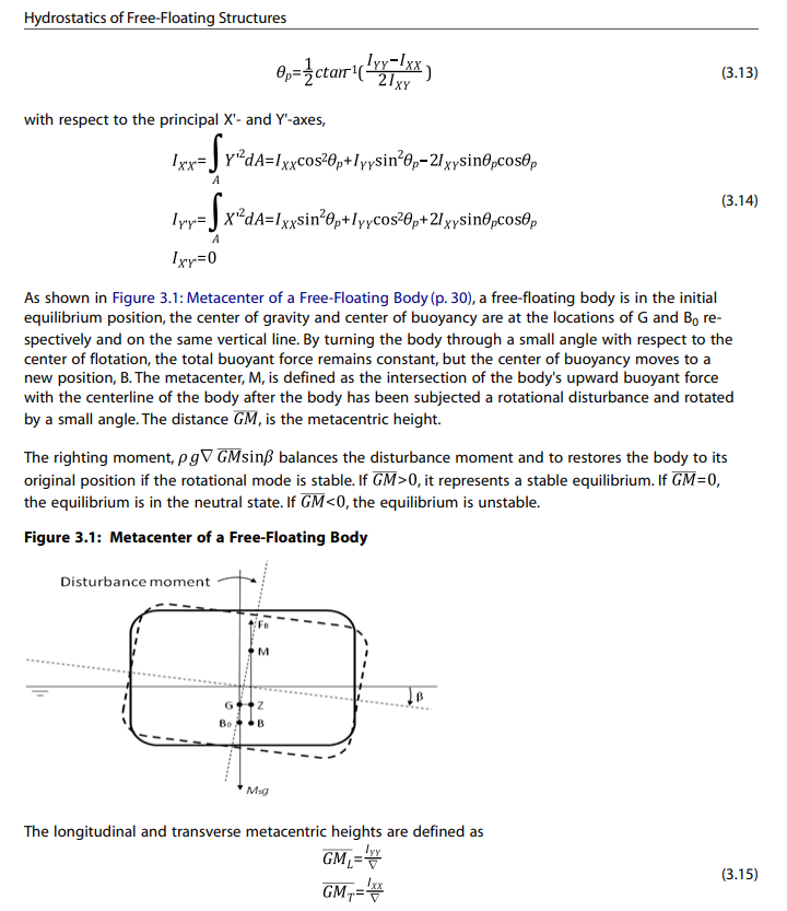
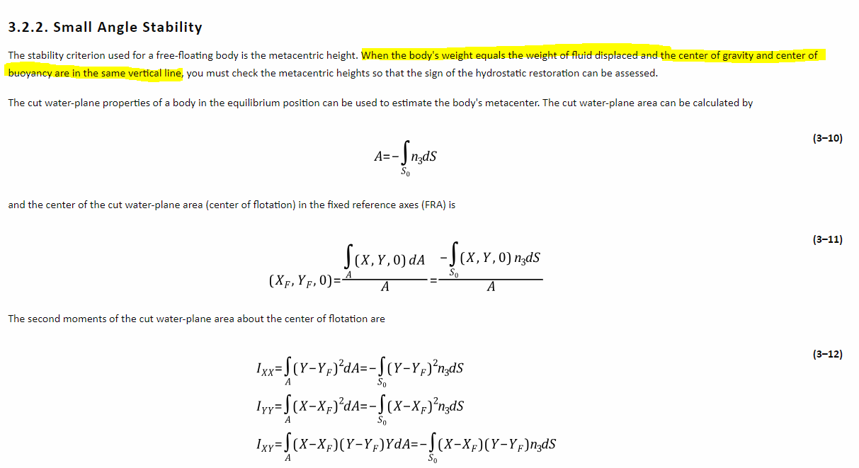
SubscriberFor a specific geometry, AQWA LINE changes the angle the principal axes of the cut water plane area make with the fixed reference axis system to 90, when calculating the hydrostatic properties. This is however not in line with the model and leads to wrong values of the second moments of area, wrong GM values and therefore wrong RAOs.
Is there a way of preventing AQWA LINE from changing the angle of the principle axis of the cut water plane area with respect to the fixed reference axis system?
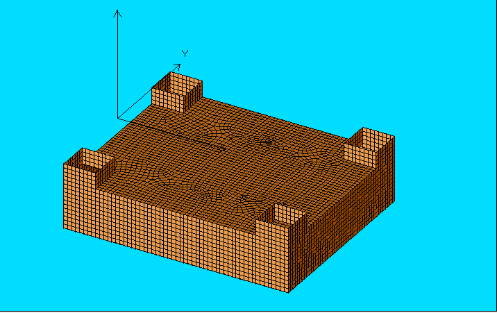
Remarkable is that for a geometry with pillars at the bow as well, this problem does not occur:
-
January 22, 2024 at 11:56 am
Shuangxing Du
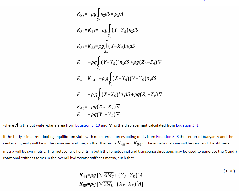
Ansys EmployeeIn Aqwa, the hydrostatic stiffness matrix is calulcated by (see Aqwa theory manual, equations 3.19-3.20)
which does not directly use the principal second moments of cut water area.
If you want to check the hydrostatic stiffness matrix, please note that if the centre of the floation and the structure gravity centre (COG) are not on the same vertical line, the second moments of the cut water area (with respect to the centre of floation) should be firstly transformed to the values with respect to the COG, then be used to calculate the hydrostatic stiffness matrix.
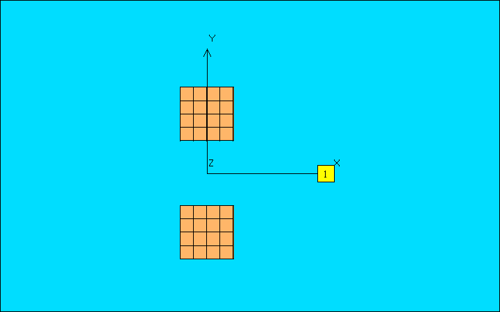
I tried a simple model as below, in which the centre of floation is at (0.0,0.0) and the COG is at (200.0, 0.0, -10.62), and did the hand calulcation of the K44 (roll-roll) and K55 (pitch-pitch),
the hydrostatic stiffness results in the Aqwa .lis file are
I cannot find anything wrong on the Aqwa calculated hydrostatic stiffness matrix which is further used for the RAO calculation. The motion RAOs should be correct.
-
January 24, 2024 at 12:57 pm
K. H.
SubscriberHi, thank you for your answer. How did you calculate the GMx and GMy without the use of the principal second moments of area of the water plane?
-
January 24, 2024 at 1:23 pm
Shuangxing Du
Ansys EmployeeThe results are from the equations given previously, i.e. Euqations (3-19) through (3-20) in the Aqwa theory manual. In your case, please check if the horizontal positions of the centre of the floation, the centre of the buoyancy and the centre of the structure COG coincide. For the model with two columns of which the horizontal locations of these three centres are not the same, please use Equation (3.19) to estimate the hydrostatic stiffness elements. They should be the same as those output in the Aqwa-Line .lis file.
-
January 24, 2024 at 1:46 pm
K. H.
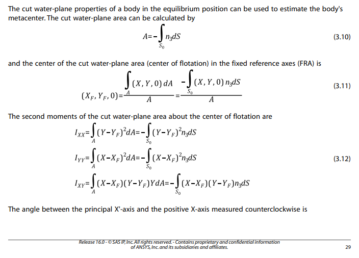
SubscriberThank you for the clarification. I indeed used the equations below from the manual to calculate the hydrostatic stiffness myself. And something goes wrong in the AQWA calculation as it gives the wrong angle of the principal axes of the cut water plane area, that should be 0 and not 90. This results in the Iyy having the value the Ixx should have. Also, it calculates a wrong Ixx, which is about 100 times too small. This results in wrong GM values and wrong hydrostatic stiffness.
The horizontal positions of the COG and COB coincide. Is there another reason or setting that I might have overlooked that could cause this error? My COG is lower than the COB by the way.
-
January 24, 2024 at 1:57 pm
-
- The topic ‘AQWA LINE: wrong angle of the principle axes of the cut water plane area’ is closed to new replies.


-
4838
-
1587
-
1386
-
1242
-
1021

© 2026 Copyright ANSYS, Inc. All rights reserved.

