TAGGED: -Ansys-Maxwell-electronics, ansys-circuit
-
-
January 10, 2024 at 3:44 pm
Zhengting.Wu
Subscriberhello there,
I want to do a failure test for my 3-Phase PMSM Model. I want to see how will the Motor acting when suddenly one Phase has open circuit fault. So I add a Voltage Controlled Switch, with a Pulse Voltage Source as the Controlling Source, to control the A phase and course a open circuit(see in the following pics).
But the Switch did not work. As you can see: the Pulse Voltage worked will, but the current of Phase A did not change along with it. I tried many times and found out that it was the Switch who wasing working.
Please help. The screenshots of circuit, settings and results are attached. THANKS!
Â
Mod setting
Switch setting
circuit
-
January 12, 2024 at 6:18 am
Reshmi Raghavan
Ansys Employee-
January 15, 2024 at 9:00 am
-
-
January 15, 2024 at 11:02 am
Reshmi Raghavan
Ansys EmployeeHello Zhengting,
Please check the switch model, if the name POS is used in the properties or not ?
-
January 15, 2024 at 11:18 am
-
-
January 15, 2024 at 11:32 am
Reshmi Raghavan
Ansys EmployeeHello Zhengting,
Â
The reference to the voltmeter has not been provided in the switch property, ID_V is empty. Please enter the name of the voltmeter used for measuring the voltage from the pulse circuit.
-
January 15, 2024 at 11:54 am
Zhengting.Wu
Subscriber
-
-
January 15, 2024 at 12:35 pm
-
January 16, 2024 at 3:40 am
Reshmi Raghavan
Ansys EmployeeHello Zhengting,
Please share the error messages, its not visible.
-
January 16, 2024 at 10:00 am
Zhengting.Wu
SubscriberHello!
Here are the error mssages when I didnt add resistors in the circuits :
 [error] Time step at 0 sec completed, process solver2d error: Internal Solver Error:  'Unable to create extnlckt_1.par file. '. Please contact Ansys technical support. (10:56:06 AM  Jan 16, 2024)
  [error] Error in estimating the memory for Auto HPC. (10:56:06 AM  Jan 16, 2024)
  [error] Simulation completed with execution error on server: Local Machine. (10:56:06 AM  Jan 16, 2024)After I added one resistor for each Phase, there were no error messages anymore, but the switch didnt work. I added the switch in Phase A but the current of Phase A remained unchanged.
-
-
- The topic ‘
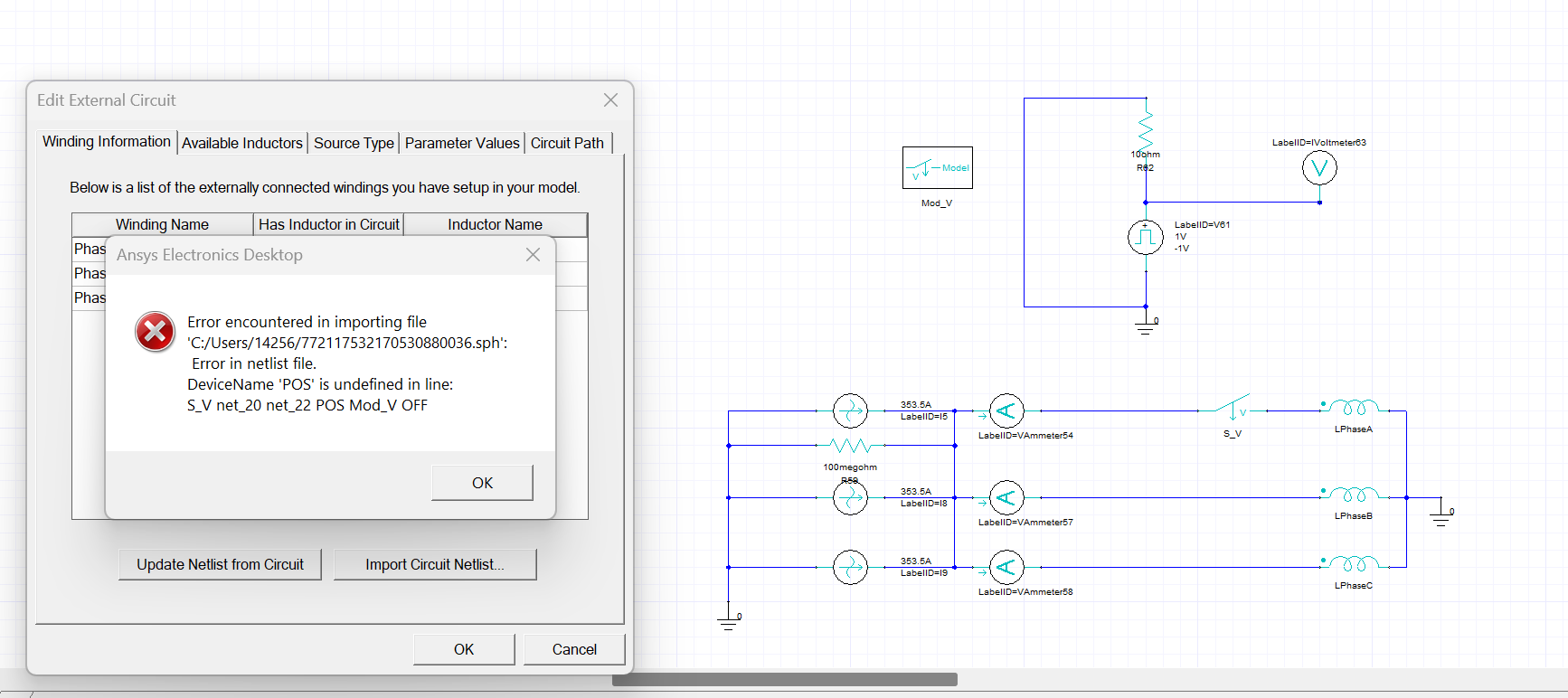
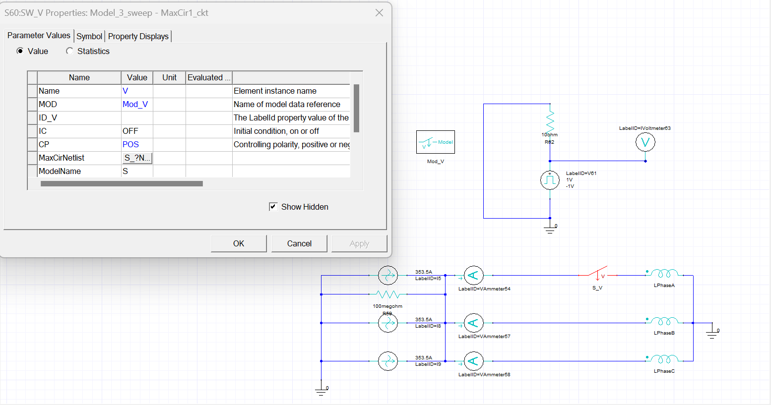
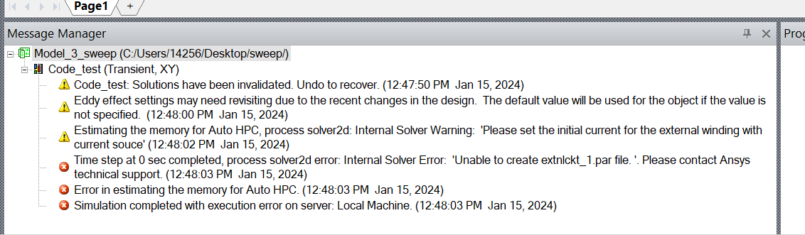
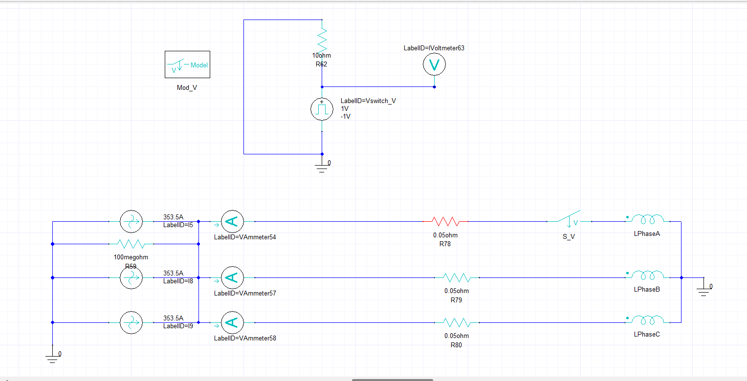
Error in Maxwell circuit Com.: Voltage Controlled Switch with Controlling Port’ is closed to new replies.
-
3767
-
1333
-
1173
-
1090
-
1014
© 2025 Copyright ANSYS, Inc. All rights reserved.