Ansys Learning Forum › Forums › Discuss Simulation › Photonics › How to find out Phase shift of transmitted wave varying radius vs wavelength › Reply To: How to find out Phase shift of transmitted wave varying radius vs wavelength
 Afroditi Petropoulou
Dear Nayem,
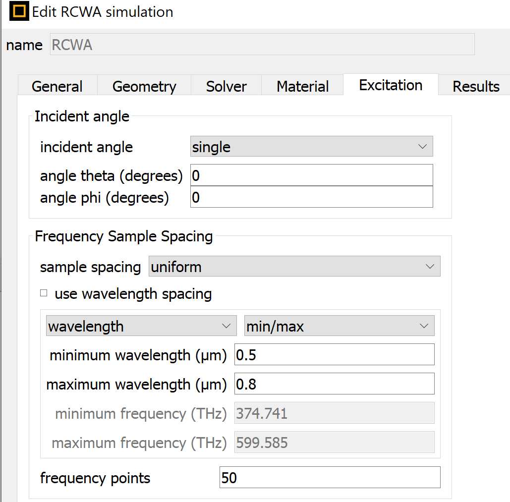
Since you are using RCWA, you don't need to add the wavelength to the sweep. It is better to have only the radius to the sweep and the wavelength can be set directly in RCWA settings as shown below:
Then you add only the radius to the sweep:
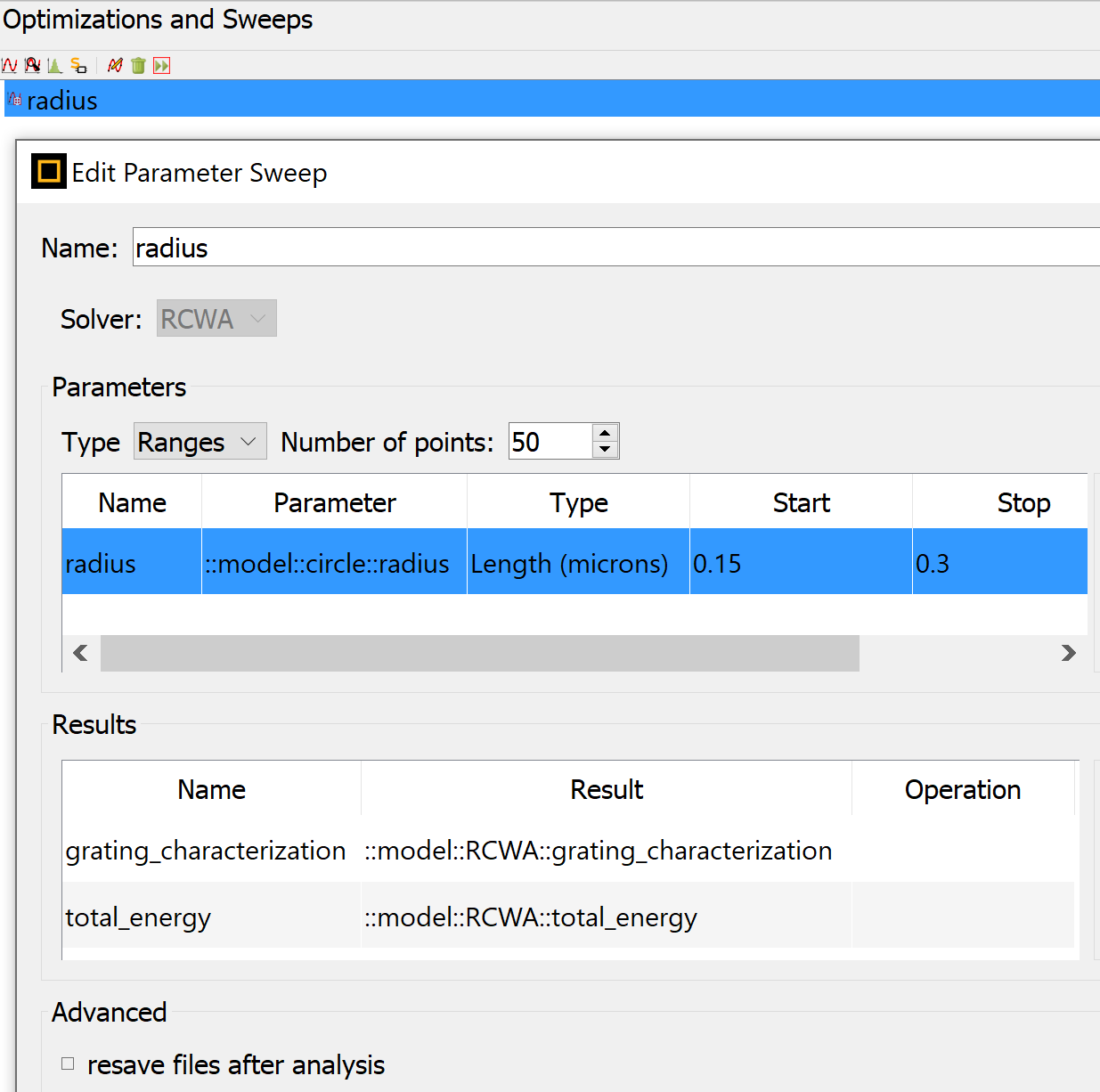
Make sure to have enough frequency and radius points in order to be able to resolve the phase shift.
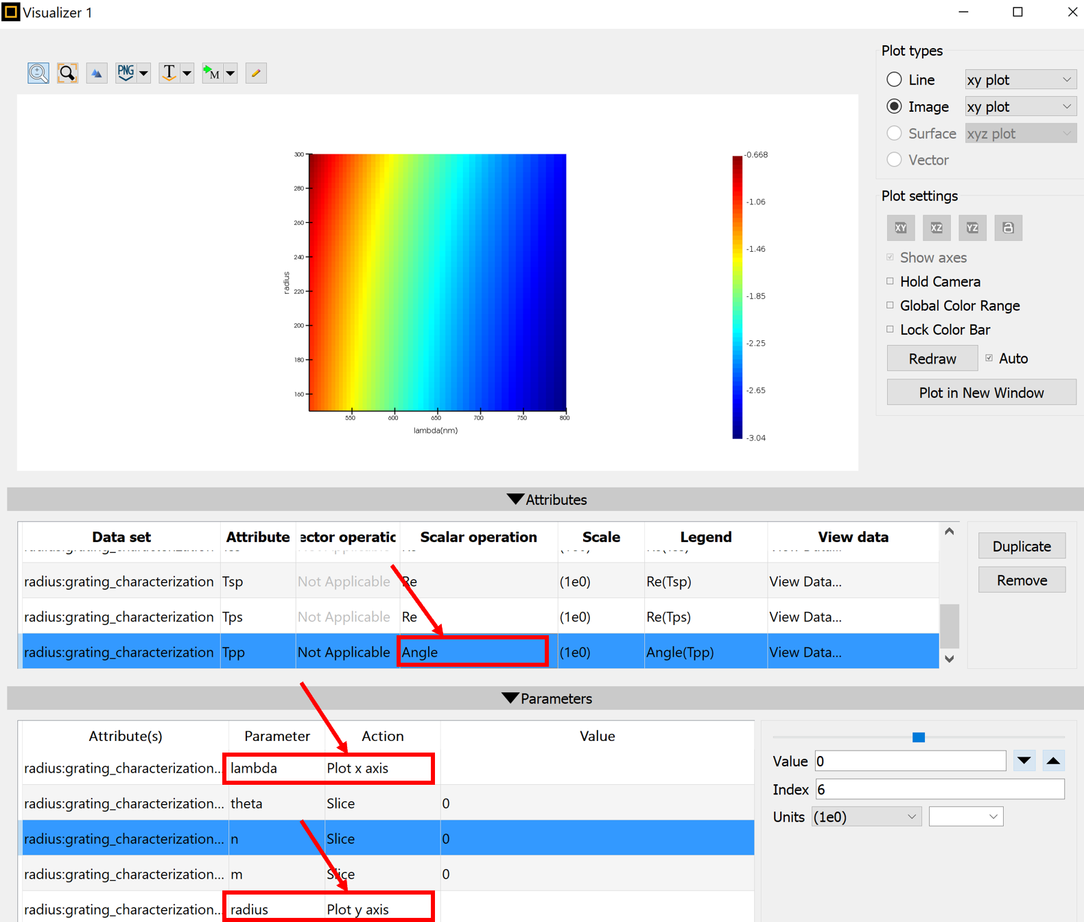
After running the sweep, you can directly get the phase plot by right-clicking on the radius sweep and visualize the grating_characterization result. In the visualization window, choose the result that you need (e.g. Tpp is shown below) and use "Angle" in the scalar operation option. In the parameters, choose to plot lambda as x axis and radius as y axis. For n and m choose the value that you are interested in (0 for 0th diffraction order is shown below):
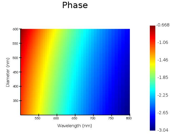
Alternatively, you can use the following script to get the phase plot (this takes into account p polarization (Tpp) but you can do the same for s polarization too):
grating_characterization = getsweepresult("radius","grating_characterization");
total_energy = getsweepresult("radius","total_energy");
radius = grating_characterization.radius;
lambda= grating_characterization.lambda;
ni = find(grating_characterization.n, 0);
mi = find(grating_characterization.m, 0);
S = pinch(grating_characterization.Tpp(:,1,ni,mi,:));
T = abs(S)^2;
phase = angle(S);
image(lambda*1e9,2*radius*1e9,phase,"Wavelength (nm)","Diameter (nm)","Phase");
The above script will give you the plot shown below:
I hope this helps.
Best Regards,
Afroditi
