-
-
January 7, 2024 at 8:48 pm
n n
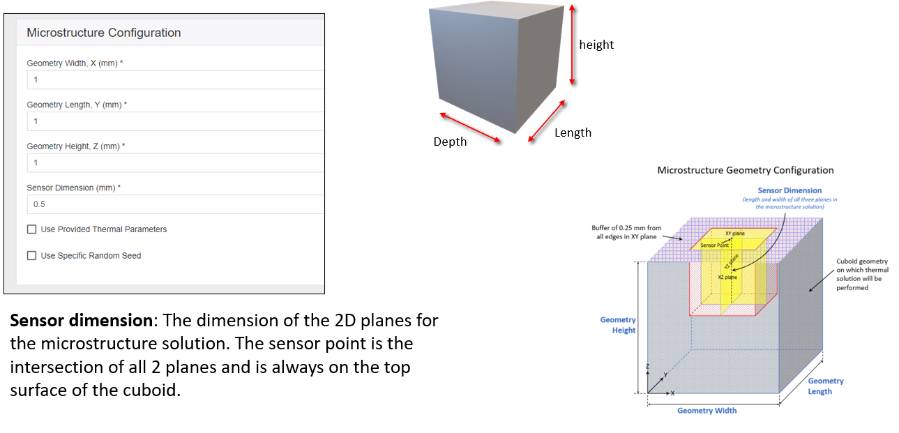
SubscriberHello, in ansys additive microstructure, description of a cube within a cube structure for microstructure modelling is confusing. If the inner cube is 1x1x1mm3 the with the buffer zones indicated the outer 'cube' must be at least 2x1.5x1.5 mm3. If the powder layer thickness is 80 um and the inner cube begins 1 mm below the outer cube explain why the microstructure shown is added powder not melted substrate? If we use these layer thicknesses, especially 80 um, can we guarantee that the substrate will not be melted? I want to know what should be the dimensions of the outer and the inner cube with respect to the sensor dimensions and high layer thickness. Please i need a response to these query. thank you.
-
January 8, 2024 at 1:24 pm
n n
SubscriberPlease i need a response
-
January 9, 2024 at 9:41 am
Ashish Khemka
Forum ModeratorHi,
Please wait for members to comment.
Thanks and Regards,
Ashish Khemka
-
January 12, 2024 at 2:16 pm
John Doyle
Ansys EmployeeThe only way to “guarantee” the validity of these simulations is thru a benchmark test. This is especially important if you are doing new work, for first time, and with no history. The Additive Science tool is intended to help establish important treads in critical results, thru simulated permutations. This helps minimize (not always eliminate) the need for testing.
You have probably seen this already, but if not, Section 1.3 (copied below) of Additive Science Users Guide, offers some observations.
In our example simulation, we added columns in the summary table to calculate depth-to-width ratio and length-to-width ratio using the simulation data. We made the following hypothetical assumptions regarding the criteria for "good-candidate" power/speed combinations:
- We want a melt pool depth that reaches at least halfway through the third layer. A penetration depth of about three layers through the thickness reduces porosity by remelting previous layers. Since our layer thickness is 40 microns (0.04 mm), that means we want a melt pool depth of at least 0.1 mm, which is a median melt pool reference depth of at least 0.06. The data that fall outside of our acceptable criteria for melt pool reference depth are shown in the yellow shaded area of the median melt pool reference depth column. These melt pools are not deep enough.
- We want a depth-to-width ratio below 0.95. The data that fall outside of our acceptable criteria are shown in the blue shaded area of the depth-to-width ratio column. These melt pools are too deep.
In fact, when the melt pool becomes too large and outside of the software's acceptable range, the Additive application will error out with the following message..."
INVALID STATE: The melt pool has become too wide and deep to produce valid results (current width = xxx microns, current depth = xxx microns). We recommend you reduce the energy input by reducing Laser Power and/or increasing Scan Speed.- We want a length-to-width ratio below 4.0. The data that fall outside of our acceptable criteria are shown in the orange shaded area of the length-to-width ratio column. These melt pools might be too long.
-
January 12, 2024 at 2:19 pm
n n
Subscriberthank you for your response what about the geometry of the inner cube and the outer cube does the inner cube has a dimensions of 1*1*1 mm and the outer cube 3*3*3 mm ?
-
January 12, 2024 at 2:22 pm
n n
Subscriberin the input of the microstructure simulation does the geometry i mention represent the geometry width length and height of the inner cube or the outer cube ?
-
January 12, 2024 at 2:35 pm
-
- The topic ‘microstructure simulation ansys additive’ is closed to new replies.


-
4663
-
1545
-
1386
-
1230
-
1021

© 2025 Copyright ANSYS, Inc. All rights reserved.


