General Mechanical

General Mechanical

Topics related to Mechanical Enterprise, Motion, Additive Print and more.

How to create paths in a curve surface in a easy way

    • user deleted
      Subscriber

      Hi guys, 


      I'm trying to create a few paths in a solid body with a curved surface by two points, but it is a slow process, and I would like to know if there is some option to relate the path with the element mesh. I attached two images to help you to understand my question. 


      Very thank in advance. 


    • mjmiddle
      Ansys Employee

      You can make an imprinted edge in the geometry modeler. Then when making the construction geometry path, choose the "Edge" option. Then in the results, you can't scope a linearized stress result but you can scope a regular stress or deformation result to the path:

    • user deleted
      Subscriber
    • user deleted
      Subscriber

      Thank you very much for your answer but I think you have not understood me, probably because I did not explain myself well enough. What I really wanted to ask is if there is any method to associate a path to the line that delimits the elements of the mesh, which do not have to correspond to the sides of the geometry, as I detail in the following image. The difficulty of the problem is that since these are curved surfaces and I have to define the path through points, I have to write down the coordinates of all the initial and final points, which is very inconvenient and slow. In this case it doesn't cause me a lot of a problem either because it is a relatively simple geometry with barely 10 paths but if it were a much more complex geometry it would be very heavy.


    • mjmiddle
      Ansys Employee

      I did understand what you wanted, and the method I suggested is the only way in Mechanical, other than making a bunch of two-point paths as you have done with node coordinates.

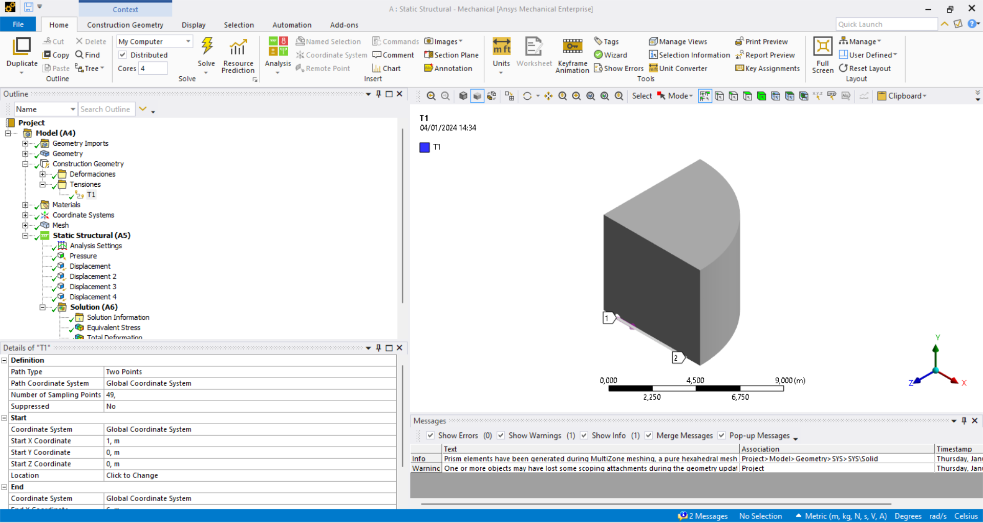
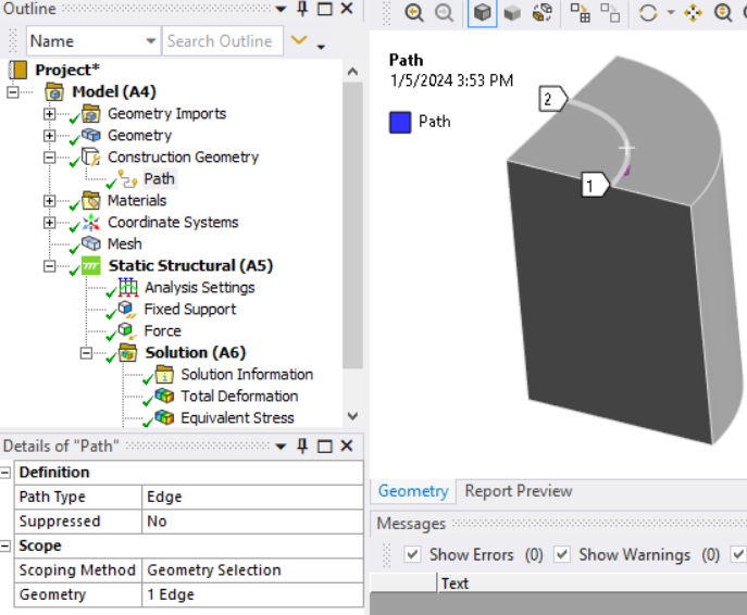
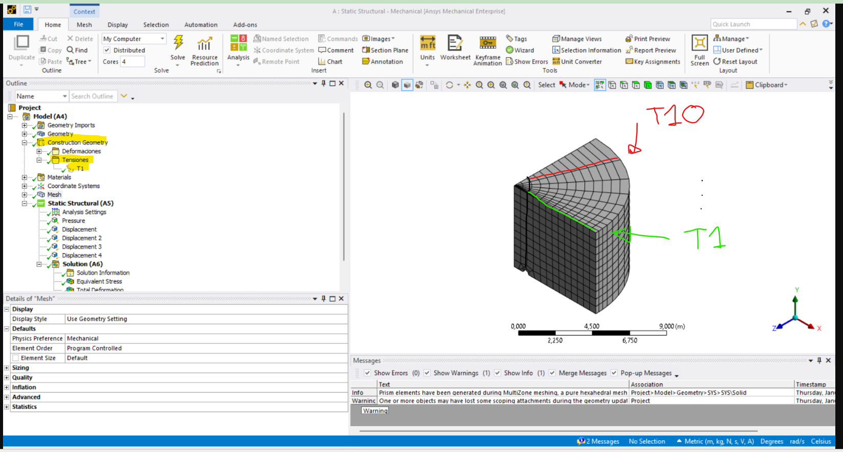
      If you make an edge imprint on a face before meshing, then it will have a mesh gridline along the edge. For your picture above, you could make a construction path using the edge at the geomtry corner at T1. For T10, you would need to make an edge imprint on the geometry face before meshing. This is the only way the Mechanical GUI allows you to do this.

      Any other method would need to be done with APDL commands. Sorry, but I don't have the commands to do this. But you would need to supply it with a list of nodes for each path, in order of the direction of each path. Or the typical way we communicate Mechanical with APDL is to send named selections which you can retrieve wth CMSEL command. But in this case you would want to make an edge imprint on the face and place the edge into a named selection. And my previous method already required you to make an edge imprint, so you might as well use that method.

      You could make a named selection of nodes. Your APDL script would need to figure out the order of the nodes to create a path.

    • user deleted
      Subscriber

      Okay, thank you very much

Viewing 5 reply threads
  • The topic ‘How to create paths in a curve surface in a easy way’ is closed to new replies.