-
-
December 29, 2023 at 4:56 pm
javat33489
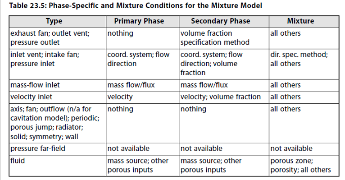
SubscriberHi all.We have two wonderful videos on calculating a centrifugal wheel (ANSYS "HOW TO"), the first is a flow calculation, the second is a cavitation calculation. It is perfectly! Thank you.Now the question. How to set a mixture pumping for a centrifugal pump? After all, one of the main conditions for the calculation is to establish the mass flow rate at the outlet of the pump, and because of this, it is not possible to correctly set the mixture at the inlet and outlet. In addition, there is help from the tutorial, which also does not include the possibility of such a calculation:Tell me what to do in such a situation? Thank you. -
January 2, 2024 at 3:53 pm
Rob
Forum ModeratorI assume this is the same as this thread? /forum/forums/topic/the-energy-problem-when-solving-cavitation-in-fluent/
-
January 2, 2024 at 4:48 pm
javat33489
SubscriberNo, that's a different topic. In this topic I ask the question of how to calculate a mixture of water + methane for a centrifugal pump. Provided that the mixture includes 90% water and 10% methane, and does not include only water as in the calculation of cavitation. The main problem is that when calculating a centrifugal pump, it is necessary to set the mass flow rate at the outlet, which is not provided for by the program when calculating the mixture. Please read the question again, I also attached a picture from the tutorial.
-
-
January 2, 2024 at 5:00 pm
Rob
Forum ModeratorIt's not necessary to set the mass flow at the outlet.
-
January 2, 2024 at 5:06 pm
javat33489
SubscriberWe are talking about a centrifugal pump. Typically, only the inlet pressure and mass flow are known. To calculate a centrifugal pump, it is necessary to set the output flow rate so that it operates in operating mode, otherwise how to catch the operating pressure?What parameters are set then?Even if you watch YOUR VIDEO, the output flow rate will also be mentioned there, and this is correctI'm waiting for a response from YOU. How to calculate a centrifugal pump using a mixture and so that it reaches the required flow rate. Your answer is too short and does not provide an answer! Please give a complete answer.
-
-
January 3, 2024 at 12:17 pm
Rob
Forum ModeratorWas mass flow monitored or set? I also suggest reviewing the T&Cs of using the forum.
Inlet mass flow is known, if you want to model cavitation you will need to carefully select the outlet pressure too.
-
January 3, 2024 at 4:29 pm
javat33489
Subscriber>>Inlet mass flow is known, if you want to model cavitation you will need to carefully select the outlet pressure too.
Can I do it this way??? Like this: 1.Make calculations on water. At the inlet the required pressure, at the outlet the required mass flow. 2.After calculating on water, I find out the outlet pressure. 3. Make a second calculation on the mixture, and set the mass flow rate at the input (which was previously at the output), and set the pressure at the output (which was obtained when solving on water)? At the input, I will set the volume fraction for methane to 0.1 (10%). What do you say?
-
-
January 3, 2024 at 4:35 pm
Rob
Forum ModeratorIt'll work, whether it's exactly what you need may need a little adjustment. Note, putting 10% by volume of gas into a pump isn't cavitation, it's highlighting that you need a gas trap!
-
January 3, 2024 at 5:14 pm
javat33489
SubscriberSir this is not a cavitation issue! That's another topic! Here I am not talking about cavitation, here I am talking about the fact that the pump pumps a mixture with 10% methane content. The calculation is carried out without taking cavitation into account.
-
-
January 3, 2024 at 5:33 pm
Rob
Forum ModeratorIn which case set inflow mass & outlet pressure may not matter as much. Unless the methane is compressible.
-
January 3, 2024 at 5:51 pm
javat33489
SubscriberCan I do it this way??? Like this: 1.Make calculations on water. At the inlet the required pressure, at the outlet the required mass flow. 2.After calculating on water, I find out the outlet pressure. 3. Make a second calculation on the mixture, and set the mass flow rate at the input (which was previously at the output), and set the pressure at the output (which was obtained when solving on water)? At the input, I will set the volume fraction for methane to 0.1 (10%). What do you say?
-
-
January 4, 2024 at 8:55 am
Rob
Forum ModeratorThat should work, try it and report back.
-
January 10, 2024 at 4:50 pm
javat33489
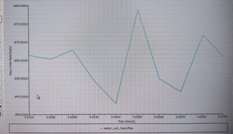
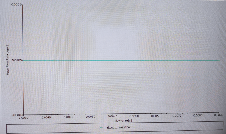
SubscriberOk I tried this:>>Can I do it this way??? Like this: 1.Make calculations on water. At the inlet the required pressure, at the outlet the required mass flow. 2.After calculating on water, I find out the outlet pressure. 3. Make a second calculation on the mixture, and set the mass flow rate at the input (which was previously at the output), and set the pressure at the output (which was obtained when solving on water)? At the input, I will set the volume fraction for methane to 0.1 (10%). What do you say?And it doesn't work that way.This works if there is no mixture. Everything works well and shows the same result as if there was flow at the outlet and pressure at the inlet.But when I add the mixture, the mass flow rate at the outlet increases sharply, but there is no methane flow rate at all:Although I indicated the mass flow rate at the inlet for water was 3.515 kg/s and for methane 0.185 kg/s. Together this is 3.7 kg/s. At the output, I specified a backflow volume fraction for methane of 0.05 (5% = 0.185 of 3.7).
-
-
January 10, 2024 at 4:57 pm
Rob
Forum ModeratorCheck how you're defining reports. If 3.5kg/s is going in and 250kg/s is leaving I'd be reviewing the flowfield.
-
January 11, 2024 at 7:50 pm
javat33489
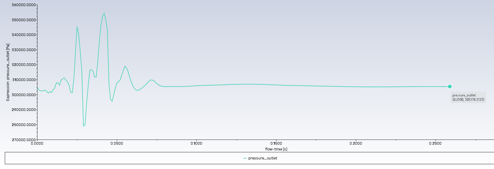
SubscriberSir, I thought I knew fluent quite well. But while solving a problem with a centrifugal pump, I realized that I had questions.As described above, initially I solved the problem on water by setting the inlet pressure and outlet mass flow (as in the video tutorial from ANSYS). As we have already found out, under this condition, it is impossible to solve the problem using a mixture because a discrepancy arises with the specified volume fraction of the second phase at the input and the flow rate of the second phase at the output.Then I tested the option with setting the mass flow rate at the inlet and the pressure at the outlet (the pressure was obtained from calculations on water). And it works well but only on water.When I decided to use the mixture, I set mass flow rates for two phases (water and methane), for water 3.515 and for methane 0.185, which in total corresponds to 3.7 - this is the flow rate of the entire medium I need. At the output for the second environment, backflow volume fraction = 0 was set. Why do we need backflow volume fraction for the second phase in this case if we have already set the input costs? As a result, I get a strong increase in pressure and flow graphs which leads to an error.Next, I decided to calculate the inlet pressure and outlet pressure. Pressures are taken from calculations on water. At the input for the second phase I set a volume fraction of 0.05 (I need 5% of the entire mixture) at the output I set a backflow volume fraction of 0 for the second phase. I track calculations using graphs in real time (pressure at inlet and outlet, flow rate at inlet and outlet, temperature at inlet and outlet and at the wheel, pressure, torque, mass flow of methane at inlet and outlet, mass flow of water at inlet and outlet) . I have a question here. Mass flow rate for methane shows 0.001 kg/s. If you calculate 5% of 3.7 kg/s it will be 0.185 kg/s. Could it be that the gas is lighter than water and the fluent shows us the weight of the gas and this is 0.001 (5% of 3.7)? Everything goes well, but after 1000 iterations all the pressures and costs increase sharply, which leads to an error.A separate question. Does volume fraction at the inlet for the second phase work differently depending on conditions? If there is pressure at the inlet then is it a percentage in the general environment or is it only in the second phase? Sir my questions may be stupid, I'm a little confused.
-
-
January 12, 2024 at 10:20 am
Rob
Forum ModeratorBackflow is to account for when mass enters the domain from an outlet. Ideally, this shouldn't happen, but when it does we need to account for it.
Volume fraction is volume fraction, so the only time it can be problematic is if the density of one phase is variable. If the gas then compresses/expands very quickly then odd things can happen.
Rapid divergence from a previous stable solution tends to suggest something is changing. With multiphase models that can mean there's a slugging effect or large bubble is dislodged from somewhere. This is why I suggest reviewing images as well as monitors: using just one may mean you're missing something.
Re the experience. I rarely model pumps and tend to leave them to colleagues who specialise in spinning applications. Equally, they tend to avoid working in some of the areas I cover.
-
January 12, 2024 at 4:42 pm
javat33489
Subscriber>>Volume fraction is volume fraction, so the only time it can be problematic is if the density of one phase is variable. If the gas then compresses/expands very quickly then odd things can happen.
This means that the volume fraction plays one role in all productions - this is the percentage in the first phase. For example, volume fraction for the second phase = 0.5 is 50 percent of the content of this phase in the first (for example, the first phase is water, the second is gas, 50% will be water and 50% will be gas).
-
January 12, 2024 at 4:54 pm
Rob
Forum ModeratorYes, but if you have a sudden pressure jump whilst mass fraction is constant volume fraction won't be and that can give a very rapid acceleration.
-
January 14, 2024 at 4:02 pm
javat33489
Subscriber>>When calculating, when I set the gas fraction volume to 0.05 (5% of the total volume), the mass flow rate of methane is 0.001 kg/s according to the schedule. If you calculate 5% of 3.7 kg/s, it will be 0.185 kg/s. Could it be that the gas is lighter than water and the fluent shows us the weight of the gas, which is 0.001 (5% of 3.7)?
Could it be that the gas is lighter than water and the fluent shows us the weight of the gas, which is 0.001 (5% of 3.7)?
-
-
January 15, 2024 at 9:52 am
Rob
Forum ModeratorFluent will report mass or volume weighting depending on what you select. So, mass and volume are accounted for, but it's the post processing that can cause some confusion, especially if a phase is compressible.
-
January 17, 2024 at 6:02 pm
javat33489
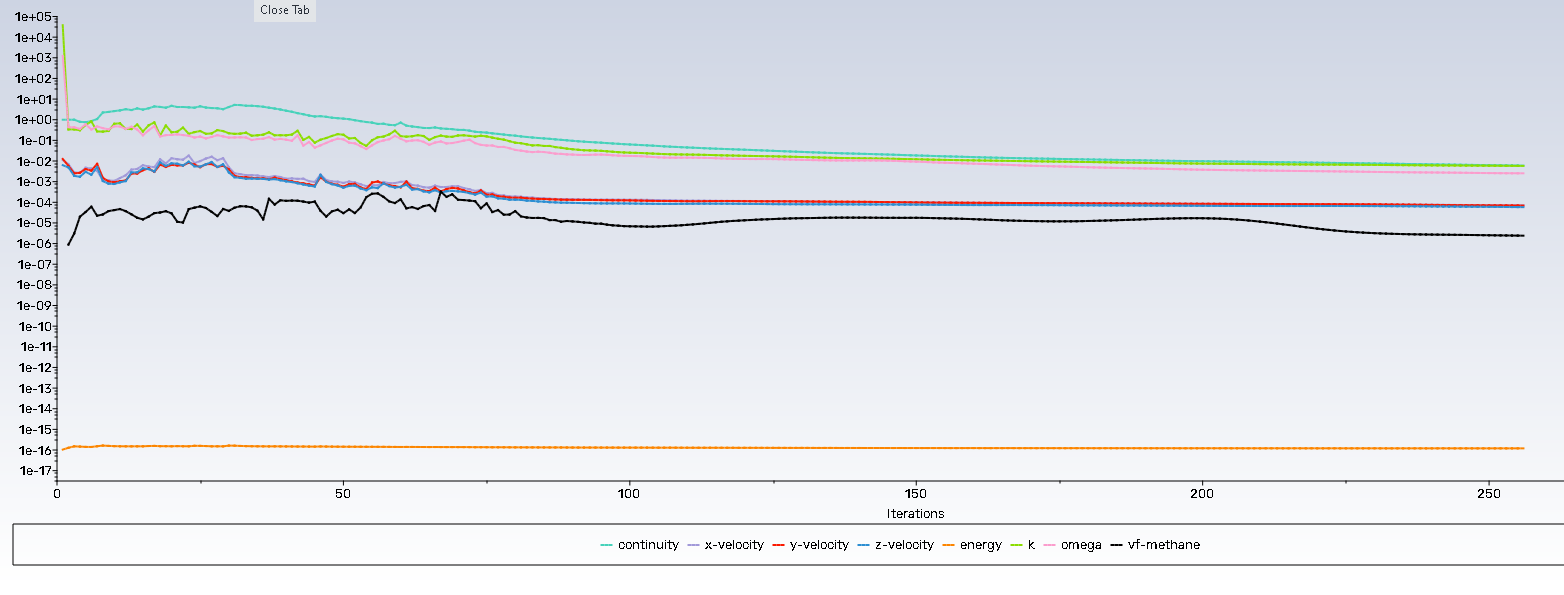
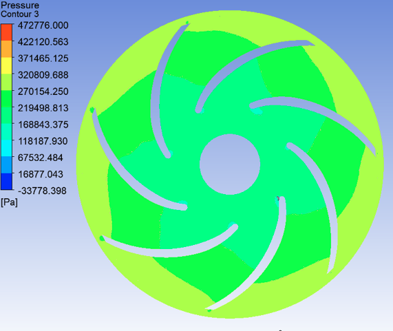
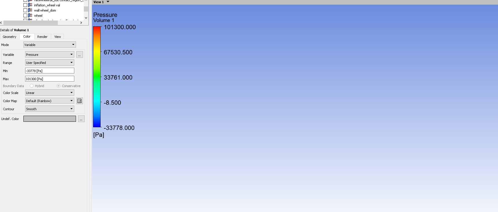
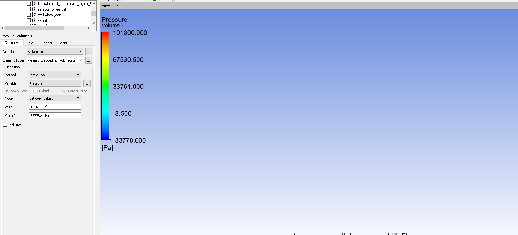
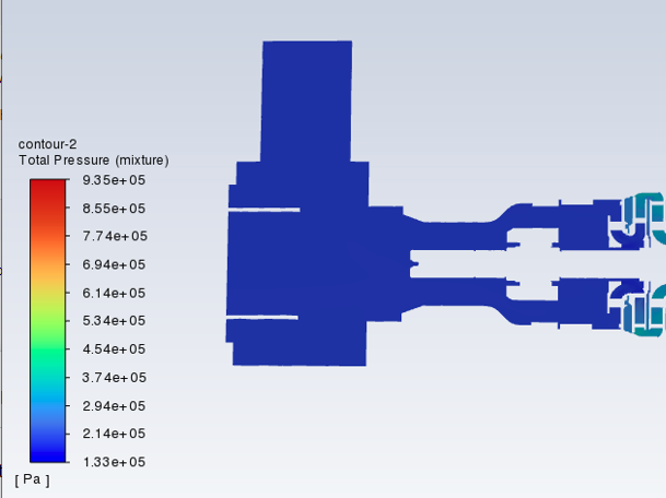
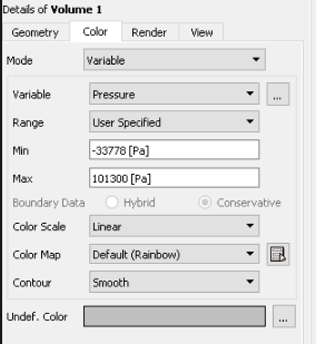
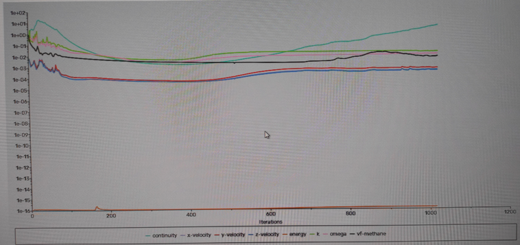
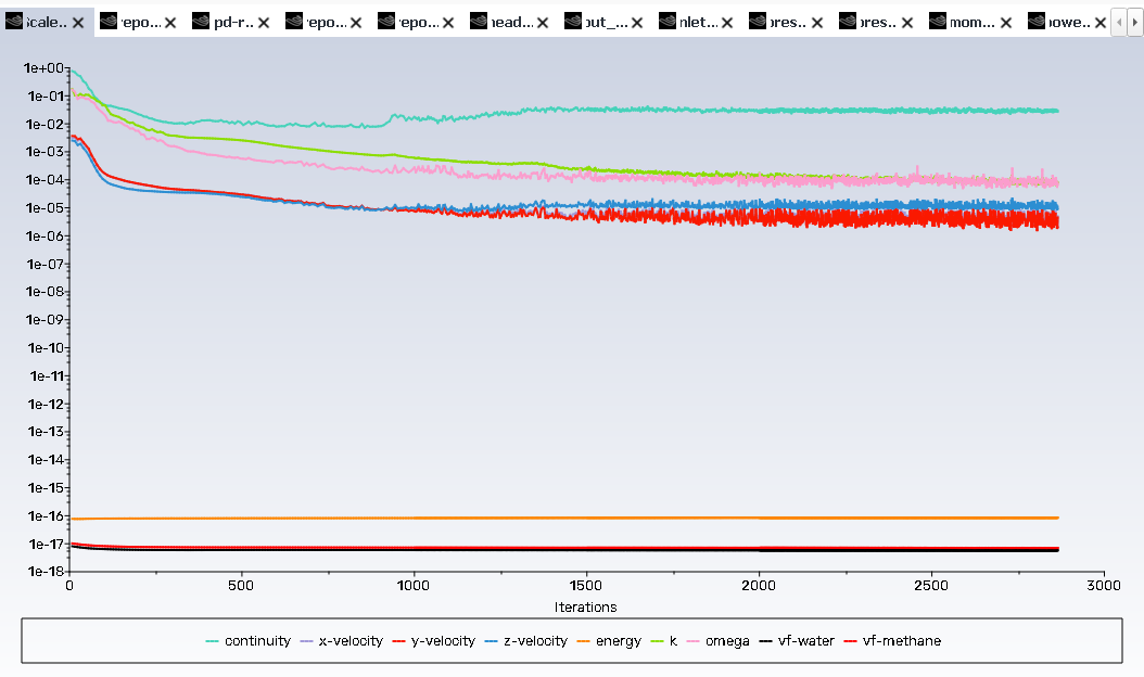
Subscriber1. Sir. I was able to analyze the water and gas. I was able to add methane under the same conditions as with water. This is what the residual graphs look like:All graphs were smooth and confirmed convergence.But when there was only water, my pressure was always more than 1 atm. This meant that there was no vacuum in the pump and, accordingly, there was no cavitation either.But when gas was added, I discovered that I had a vacuum zone, this is negative pressure:This is SFD POST.This pressure is not visually visible in the section, but when I turn on the isovolumes of negative pressure or pressure below 1 atm, the picture is empty! Why?It is noteworthy that when I look at the TOTAL PRESSURE sections in the fluent itself, it does not show negative pressure at all:2. To get rid of this negative pressure, I decided to increase the pressure at the inlet and outlet by 1 atm. But now, with the solution, the continence increases and the pressure in the body increases inappropriately to more than 100 MPa or more. Why is this happening?Sir. What should I do?
-
-
January 18, 2024 at 11:42 am
Rob
Forum ModeratorFirst off you need to find the low pressure regions - how did you set up the isosurface?
-
January 18, 2024 at 4:50 pm
-
January 18, 2024 at 4:52 pm
javat33489
SubscriberSir. I was wrong again. When I said that I managed to do the calculation but I don’t see any negative elements, only 300 iterations have passed. I waited until 1000 and the calculation failed again with the error.I noticed that after 1000 iterations the inlet pressure begins to drop.I use the setting of inlet speed and outlet pressure (I found them when calculating on water). At first everything goes perfectly, but then the inlet pressure drops.
-
-
January 18, 2024 at 5:21 pm
Rob
Forum ModeratorSo plot results at around 980 iterations to see what's going on.
Remember that by fixing the inlet flow you may create a positive or negative pressure as the pump drags flow though it (ie have you got enough flow to balance the pump impellor spin speed) that's then pushed out the back end.
-
January 18, 2024 at 5:36 pm
javat33489
SubscriberSir, at 980 iterations it’s about the same as what I wrote. The postprocessor shows negative pressure; it is not visible on the cross-section. And also the isofields do not see it (see screenshots above).I used the setup: inlet speed and outlet pressure because this is the only setup that works.The speed found allows me to get the flow rate I need at 3.7 l/s.If I use pressure-pressure, the pressure at the outlet of the pump is always greater and it forces the liquid back through the inlet - this is incorrect.If I use the input flow rate, I need to set the flow rate for methane by calculating its mass - this is difficult and there is a possibility of error.And if I set the inlet speed, the simplest thing is to set the volume fraction for the gas and the fluent itself will calculate how much it is."that by fixing the inlet flow you may create a positive or negative pressure as the pump drags flow though it (ie have you got enough flow to balance the pump impellor spin speed) that's then pushed out the back end" - yes sir, me too I thought so. I think most likely there is not enough pressure at the inlet and outlet, so the calculation stops with an error.I am planning:- increase outlet pressure.- by increasing the outlet pressure, the inlet pressure will also increase and the speed will remain the same, which will allow me to maintain the required flow rate.- I will need to iteratively increase the pressure until the calculation stops stopping, thus selecting the required operating pressure for the mixture.What do you think about my idea sir? -
January 22, 2024 at 4:54 pm
javat33489
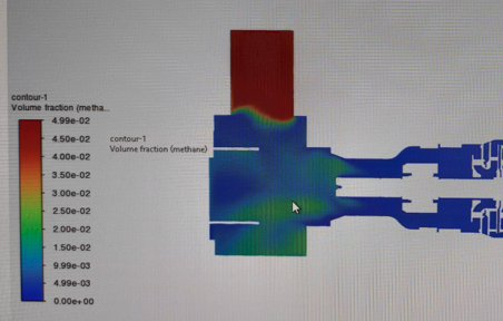
SubscriberSir, I have figured out the problem statement.You can use 2 options: inlet speed and outlet pressure or inlet flow and outlet pressure. To set the flow rate, you need to convert both phases to kg/s. Then both options work and show the same data.Both methods have the same problem!1. When using inlet speed and outlet pressure, you need to select the right pressure so that it matches the speed, I selected it and even took more with a margin. But always after about 700 iterations the continuity begins to grow and after 3000 iterations it generates an error. With this method, I immediately see on the graph the mass flow of gas and water at the inlet and outlet.2. When using inlet flow and outlet pressure. At first everything is also good. But always after about 700 iterations the continuity begins to grow and then the error. In addition, with this method, I see the mass flow rate at the inlet and outlet of water, and gas only at the inlet; at the outlet, the mass flow rate of gas shows 0.After 1000 iterations, this is the picture of methane volume fraction:Sir. Why is continuity growing? When I solve a problem only on water, it is solved perfectly.
-
-
January 24, 2024 at 11:59 am
Satish Patange
Ansys EmployeeAdditional note when modeling pumps with incompressible liquid: The constant density of the fluid will show low negative pressures where flow accelerates. This is expected from such a numerical simulation. Typically at such locations, the cavitation would occur so pressure gets clipped just around vapour pressure. Usually this low negative pressure region is small and localized so its ignored when doing performance computations.
If the low negative pressure values are of concern, then you would need to model cavitation to clip this.
-
January 24, 2024 at 4:40 pm
javat33489
SubscriberYour answer is not at all appropriate. It seems you didn't read the entire topic. I have another problem!
-
-
January 24, 2024 at 7:01 pm
javat33489
SubscriberColleagues. Could you write what you would do in my place with this task? I've exhausted all ideas.So let me remind you what happened.1. I made a calculation using water for a centrifugal pump. I used pressure at the inlet and flow at the outlet. I selected the inlet pressure so that there was no vacuum in the pump housing. Everything is fine.2. Next I need to add 5% methane. I use a mixture, the base phase is water, the second is methane.It is no longer possible to use the output flow rate, because you need to set the methane flow rate at the output and volume fraction at the input, which introduces dissonance into the problem statement.Then I have two options: 1. Flow at the inlet and pressure (found when calculating on water) at the outlet. 2. Inlet velocity (found when calculating on water) and outlet pressure (found when calculating on water).But when I use any of these options, my continuity increases and the calculation ends with an error. And when I use inlet flow and outlet pressure, the methane phase does not reach the outlet at all.As I wrote earlier, I used many settings to avoid this (read above), but nothing helps.I've exhausted all my ideas and would like to listen to yours. Thank you. -
January 25, 2024 at 1:55 pm
Satish Patange
Ansys EmployeeI would suggest to have a read through the following section of the help manual, which talks about modeling strategies:
25.8. Solution Strategies for Multiphase Modeling (ansys.com)
Generally its better to start with simpler models and numerics; obtain a reasonably converged solution and then build up the compexity of the multiphase simulations and restart the simulation. These types of simulations could necessitate long run times with timesteps being ramped from small values to larger values equivalent to the residence time in the domain so as to achieve mass, momentum & volume fraction balance.
-
January 25, 2024 at 4:22 pm
javat33489
SubscriberI know this tutorial very well. You're not helping me. You give simple advice. I am solving a difficult problem, I need experienced help and advice on what to do.
-
-
January 25, 2024 at 5:22 pm
Rob
Forum ModeratorIn Moderator role.
Given Satish knows far more about pumps than I do, I suggest being very careful with how you phrase replies regarding experience. If you care to review the T&Cs on here you'll notice points covering respect, politeness and that there are limits on how much specialist help that Staff can provide.
In engineer role.
Now, if flow in and pressure out aren't working, have you considered compressible gas? It's not clear what you have and haven't tried, nor whether you've looked at lower speeds and mesh quality (that may be in a different thread).
Now, my last comment on this. Consider this a warning. If I have to return to this thread in my Moderator role you will find it closed.
-
January 26, 2024 at 2:08 am
javat33489
SubscriberOkay, sorry, I understand you.
One more note that may suggest an answer.
During long tests, I noticed that continuity begins to increase after the pump reaches operating mode, that is, when all the graphs become smooth and no longer fluctuate and the flow levels out. Why is this happening? It would seem that the graphs should continue to remain smooth for many steps.
-
January 29, 2024 at 5:18 pm
Satish Patange
Ansys EmployeeThere can be various reasons for continuity eqn divergence.
Could you give more information about your physics setup: What multiphase model are you using? Is the gas modeled as compressible? What BCs are you currently using? Are you solving this as steady state with MRF for the rotor-stator?
A few screenshots of the setup will be helpful showing the setup.
In the cross section plot with the methane vf, where are the inlet, impeller and outlet? Also include a picture of the mesh on this plane.
-
January 29, 2024 at 6:14 pm
javat33489
SubscriberI'm using a mixture model. I need a mixture because... water comes immediately with gas.I'm using incompressible gas.No I don't use steady state. I use transient analysis.I use the setting pressure at the inlet and mass flow at the outlet.I managed to solve the problem using the SIMPLEC method, with great relaxation:Only the pressure makes big leaps:Otherwise everything was set.I achieved a solution only in the first orders of the SIMPLEC method. What do you think about this? -
January 29, 2024 at 6:35 pm
javat33489
SubscriberPlease tell me why you advised making the gas compressible? Could this help?
-
January 29, 2024 at 6:36 pm
javat33489
SubscriberAnd also look at the second question that interests me. After I managed to solve this problem (as I described above), I increased the amount of gas, which I described here:
/forum/forums/topic/increasing-the-gas-fraction-in-the-fluent-mixture/
what do you say?
-
February 1, 2024 at 4:49 pm
javat33489
SubscriberSir?
-
-
-
February 1, 2024 at 4:53 pm
Rob
Forum ModeratorCompressible gas gives the solver some volume variability to balance inflow and pumping flow.
-
- The topic ‘Calculation of a centrifugal pump in fluent’ is closed to new replies.


-
4607
-
1515
-
1386
-
1209
-
1021

© 2025 Copyright ANSYS, Inc. All rights reserved.

