Fluids

Fluids

Topics related to Fluent, CFX, Turbogrid and more.

Validation of airfoil Lift and Drag forces

    • Aras karimi
      Subscriber

      Hi Ansys community,

      I have been working on the validation of my results with the experiment results for many months and I am not getting the answer.

      I am trying to validate the lift and drag coefficients of a symmetrical 3D airfoil. After studying the independence of the solution from the mesh, I chose the final mesh and proceeded to obtain the lift and drag coefficients at different angles of attack. Incompressible flow and Re=120,000.

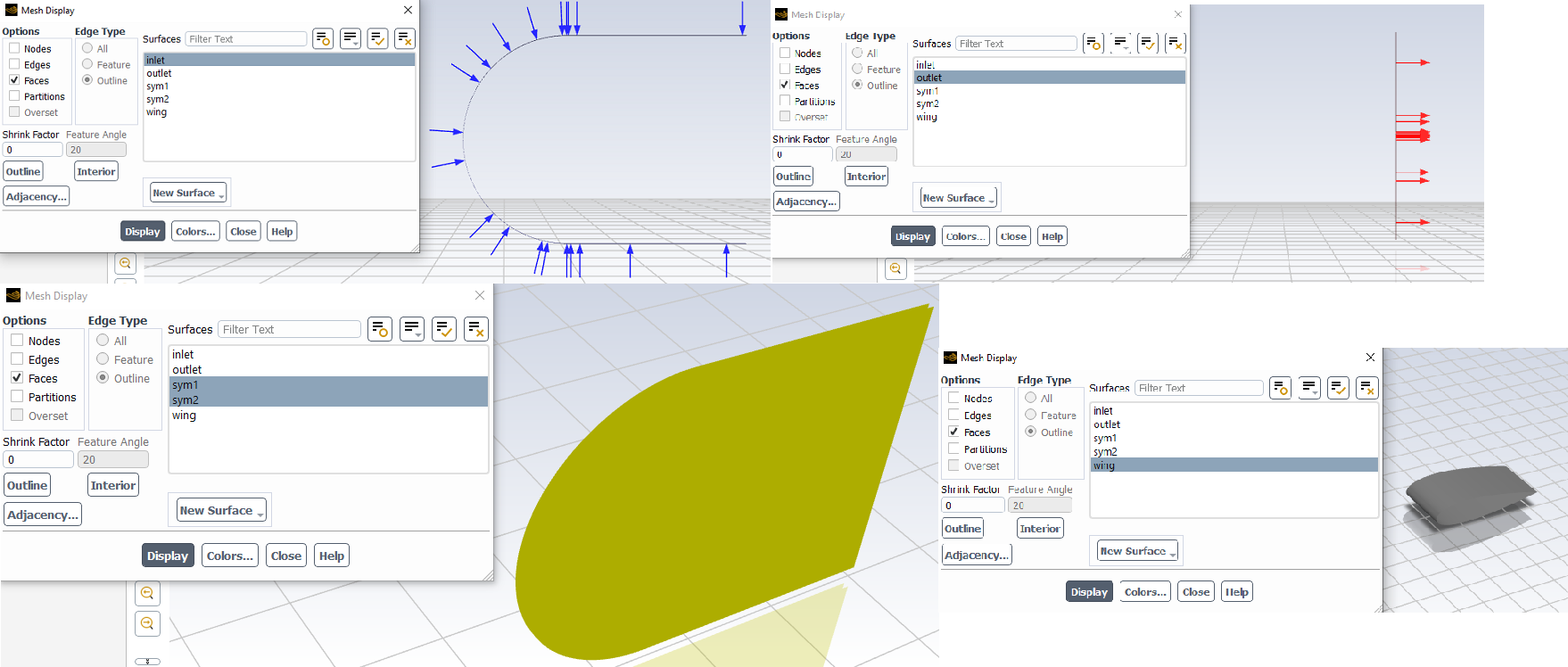
      I created a structured mesh with hexahedral elements in ICEM that has a Y+ of less than one as shown below. I use the K-Omega SST turbulence model.

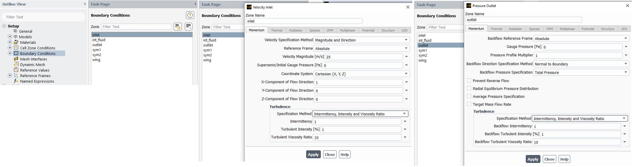
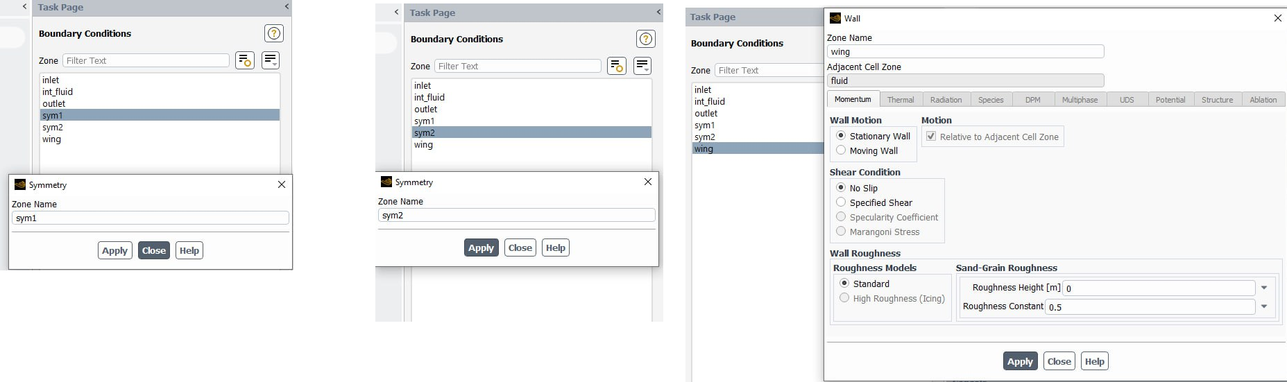
      I used the following boundary conditions:


      Now, after calculating the lift and drag coefficients at different angles of attack, I drew its graphs as follows: (Blue curves)


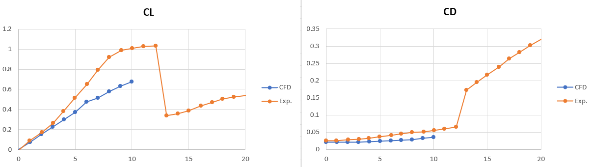
      According to the figure above, the lift and drag coefficients are very different from the experimental results.

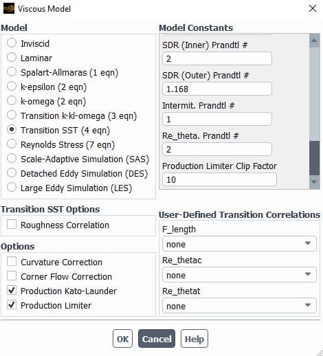
      Ansys community, I checked all types of meshes and my answer did not change, so I can say that the problem is not mesh. I think there is a problem in the setup settings. I set the settings of the method as follows:

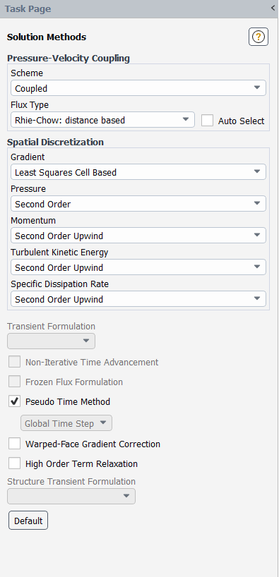
                         I even used Quick and Muscle discretizations, but I don't get good answers.

      Please check my case and geometry file to see what's wrong. I have no time left and I am very worried.

      I thank you a thousand times.

    • Essence
      Ansys Employee

      Hello,

      What is the Mach number in your domain?

      • Aras karimi
        Subscriber

        Mach= 0.073

    • Essence
      Ansys Employee


      Hello,

      Which type of initialization did you use? Did you try FMG initialization? Select High Order Term Relaxation and select Auto select for the Flux type in Methods section. Note that, you need to have at least 10-15 inflation layers with growth rate not more than 1.15 in the mesh. The aspect ratio needs to be less than 300 if possible.

      What BCs did you apply and how? Did you take the angle of attack into the consideration and apply the respective X, Y and Z components in the BCs? Could you share the screenshot of BCs and turbulence models? Also, how are you determining the Cl and Cd values. Please show the equations you use in the Fluent.


      • Aras karimi
        Subscriber

        I initialized using hybrid. I did not use FMG initialization.

        I had sent the image of the boundary conditions used in the previous messages. And I am sending it again:


        According to the figure above, the boundary conditions include velocity inlet, pressure outlet, symmetry and wall.

        I enter the angle of attack values in the Velocity Inlet Boundary Condition section.

        I use the following turbulence model:

        In the method section, I activated the high order term relaxation options and also the autoselect option for flux type, but there was no change in my results.

        What else should I do?

    • Essence
      Ansys Employee

      By the BCs, I meant to ask you the BC panels. Please show the boundary condition panels.

      • Aras karimi
        Subscriber

        The boundary conditions are as follows:


    • Essence
      Ansys Employee

      Yes, this is what I wanted to see. Thanks.

      I see that you have used velocity inlet BC instead of pressure-farfield BC. Any reason? I also see that you have not applied the X, Y and Z components (angle directions) properly. Please go through the Ansys guide link as provided. Though the link demonstrates the Ma = 0.8, it will give you a good idea on setting up the case.

      https://ansyshelp.ansys.com/account/secured?returnurl=/Views/Secured/corp/v232/en/flu_tg/flu_tg_oneram6_wing.html

      • Aras karimi
        Subscriber

        I set the borders of the semicircle on the left, top and bottom to Velocity Inlet. This is a common practice and many articles have done the same. Why is it wrong?

        Yes, the photo sent was at a zero-degree angle of attack, and that's why I haven't adjusted the X and Y values. At different angles of attack I set its values to the correct inlet velocity.

        I have already seen the video link you sent. It did not help me.

    • Essence
      Ansys Employee

      Although the velocity inlet BC can be used for incompressible and compressible flows, you need to note that the total (or stagnation) pressure is not fixed but will rise (in response to the computed static pressure) to whatever value is necessary to provide the prescribed velocity distribution.

      Hence, please try the pressure-farfield BC. Also note that, this boundary condition is applicable only when the density is calculated using the ideal-gas law. Using it for other flows is not permitted. To effectively approximate true infinite-extent conditions, you must place the far-field boundary far enough from the object of interest. For example, in lifting airfoil calculations, it is not uncommon for the far-field boundary to be a circle with a radius of 20 chord lengths.

Viewing 5 reply threads
  • The topic ‘Validation of airfoil Lift and Drag forces’ is closed to new replies.