TAGGED: 1D-tension-only-element, bridge, cable, link180
-
-
December 6, 2023 at 10:57 pm
Dan Woods
SubscriberHi,
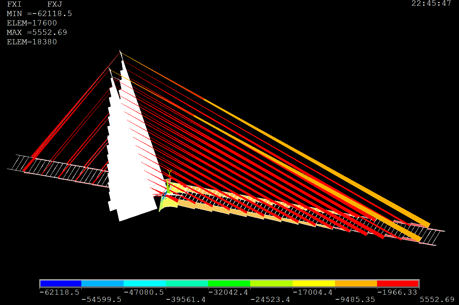
I'm building a cable stayed bridge in ANSYS mechanical and struggling to get LINK180 to act in tension only.
I've used SECCONTROL,,1 after defining the link element with SECTYPE but based on my output it doesn't seem to have worked.
When I plot FXI and FXJ the longest link element still seems to be taking a compressive load as its colour is within the -1966 to -9485 kN range. Am I using SECCONTROL incorrectly or is there some issue with my plot? All I did was make an etable with FXI and FXJ and then plot it with PLLS. The compressed cables are definitely the correct section since I can select them with the section ID.
For more context this is my definition of the link section:
SECTYPE,4,LINK,,Cable
SECDATA,0.12566370614359174
SECCONTROL,,1Any help would be appreciated thanks.
-
December 7, 2023 at 7:40 pm
wrbulat
Ansys EmployeeHi Dan,
I think you found a problem with the SECONTROL command. I could be wrong but after a fair bit of testing it appears that the command fails to establish tension/compression link settings for both LINK180 and CABLE280. The default for LINK180 is that it carries both tension and compression, and it seems SECONTROL,,1 is NOT changing this (consistent with your observation). The default for CABLE280 is the ratio of compressive stiffness to tensile stiffness is 1e-5. SECONTROL,,,,,CV3 appears NOT to change this either, but for CABLE280, the default behavior is to only very slightly carry tension - probably a pretty reasonable representation of reality So for now this is the best option I can recommend.
I created two test cases, each a vertical "tower" that is laterally supported by cables (think of a radio transmitting tower).
My LINK180 test case follows:
fini/cle/vup,1,z/vie,1,3,2,1/esha,1C********************************************C*** PARAMETERSC********************************************pi=acos(-1)h_tower=25 ! TOWER HEIGHTa_tower=0.1 ! TOWER SQUARE CROSS SECTION EDGE LENGTHE_tower=2e11 ! TOWER ELASTIC MODULUSnu_tower=0.3 ! TOWER POISSON'Sn_cables=3 ! # OF CABLESh_cable=15 ! HEIGHT OF CABEL ATTACHMENT TO TOWERr_cable=10 ! RADIUS OF CABLE ANCHORS TO GROUNDrcross_cable=0.01 ! RADIUS OF CABLE CROSS SECTIONE_cable=2e11 ! CABLE ELASTIC MODULUSnu_cable=0.3 ! CABLE POISSON'Sesz=1 ! MESH SIZEFX_top=1000 ! X COMPONENT FORCE AT TOP OF TOWERC********************************************C*** MODELC********************************************/prep7et,1,188 ! TOWER ATTRIBUTESmp,ex,1,E_towermp,nuxy,1,nu_towersect,1,beam,rectsecd,a_tower,a_toweret,2,180 ! CABLE ATTRIBUTESmp,ex,2,E_cablemp,nuxy,2,nu_cablesect,2,linksecd,pi*rcross_cable**2secontrol,,1 ! TENSION-ONLYlsel,none ! TOWER GEOMETRYk,1k,2,,,h_cablek,3,,,h_towerl,1,2l,2,3dk,1,uxdk,1,uydk,1,uzdk,1,rotzfk,3,fx,FX_toplatt,1,1,1,,,,1lsel,none ! CABLE GEOMETRYcsys,1*do,i,1,n_cablesk,3+i,r_cable,(i-1)*(360/n_cables)l,3+i,2dk,3+i,uxdk,3+i,uydk,3+i,uz*enddolatt,2,2,2,,,,2alls ! MESHesiz,eszlmes,allfiniC********************************************C*** SOLVEC********************************************/soluacel,,,9.81nsub,5,25,5outr,all,allnlge,onpivc,offallssavesolveC********************************************C*** POST PROCESSC********************************************/post1/pbc,rfor,,1/pbc,f,,1/esha,10/vsc,1,2.5plns,u,x/eofMy CABLE280 test case follows:
fini/cle/vup,1,z/vie,1,3,2,1/esha,1C********************************************C*** PARAMETERSC********************************************pi=acos(-1)h_tower=25 ! TOWER HEIGHTa_tower=0.1 ! TOWER SQUARE CROSS SECTION EDGE LENGTHE_tower=2e11 ! TOWER ELASTIC MODULUSnu_tower=0.3 ! TOWER POISSON'Sn_cables=3 ! # OF CABLESh_cable=15 ! HEIGHT OF CABEL ATTACHMENT TO TOWERr_cable=10 ! RADIUS OF CABLE ANCHORS TO GROUNDrcross_cable=0.01 ! RADIUS OF CABLE CROSS SECTIONE_cable=2e11 ! CABLE ELASTIC MODULUSnu_cable=0.3 ! CABLE POISSON'Scv3=1 ! STIFNESS RATIO (COMPRESSION TO TENSION)esz=1 ! MESH SIZEFX_top=1000 ! X COMPONENT FORCE AT TOP OF TOWERC********************************************C*** MODELC********************************************/prep7et,1,188 ! TOWER ATTRIBUTESmp,ex,1,E_towermp,nuxy,1,nu_towersect,1,beam,rectsecd,a_tower,a_toweret,2,280 ! CABLE ATTRIBUTESmp,ex,2,E_cablemp,nuxy,2,nu_cablesect,2,linksecontrol,,,,,cv3secd,pi*rcross_cable**2secontrol,,,,,cv3 ! STIFNESS RATIO (COMPRESSION TO TENSION)lsel,none ! TOWER GEOMETRYk,1k,2,,,h_cablek,3,,,h_towerl,1,2l,2,3dk,1,uxdk,1,uydk,1,uzdk,1,rotzfk,3,fx,FX_toplatt,1,1,1,,,,1lsel,none ! CABLE GEOMETRYcsys,1*do,i,1,n_cablesk,3+i,r_cable,(i-1)*(360/n_cables)l,3+i,2dk,3+i,uxdk,3+i,uydk,3+i,uz*enddolatt,2,2,2,,,,2alls ! MESHesiz,eszlmes,allfiniC********************************************C*** SOLVEC********************************************/soluacel,,,9.81nsub,5,25,5outr,all,allnlge,onpivc,offallssavesolveC********************************************C*** POST PROCESSC********************************************/post1/pbc,rfor,,1/pbc,f,,1/esha,10/vsc,1,2.5plns,u,x/eofCopy these into two separate files and read them individually into MAPDL interactively. They solve instantly and leave you looking at a post processing plot including reaction force symbols from which you can infer whether or not the forward cable (the one extending in global x direction) is carrying tension in response to the x component force applied at the top of the tower. We of course expect it to go slack.
Thanks for keeping us honest,
Bill
-
December 8, 2023 at 6:57 am
Dan Woods
SubscriberThanks for the response, swapping to cable280 does seem to have solved my problem.
-
December 10, 2023 at 12:07 pm
Dan Woods
SubscriberHi Bill,
Being forced to use nonlinear analysis as I'm forced to use cable280 is actually causing some problems. Are there any other alternative ways of modelling a tension only axial element? How did this bug even go unnoticed, does noone use link180?
-
-
- The topic ‘Issue with tension only LINK180 element’ is closed to new replies.


- The legend values are not changing.
- LPBF Simulation of dissimilar materials in ANSYS mechanical (Thermal Transient)
- Convergence error in modal analysis
- APDL, memory, solid
- Meaning of the error
- How to model a bimodular material in Mechanical
- Simulate a fan on the end of shaft
- Real Life Example of a non-symmetric eigenvalue problem
- Nonlinear load cases combinations
- How can the results of Pressures and Motions for all elements be obtained?

-
3977
-
1461
-
1272
-
1124
-
1021

© 2025 Copyright ANSYS, Inc. All rights reserved.


