-
-
December 5, 2023 at 10:30 pm
Diogo Martinho
SubscriberHey all,
I am modelling mass transference between phases and as I couldnt get the simulation to converge I started to ""debug"". Although, I am not entirely sure this is the source of my convergence problem, it is something that I would like to know how to fix it.
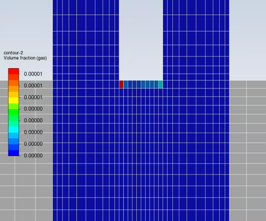
It is an eulerian-eulerian simulation where liquid is primary phase and gas the secondary phase. I already tried several things, but the picture below is the result of solving only the primary phase (disabing the vof equation and the gaseous species) and as soon as that converged I just inserted at the inlet a gas fraction of 1e-7 and calculate my solution again.
All the domains are porous (but I am not sure that is important here). But as you can see, without having any kind of gas source terms, those cells near the wall take values quite different from the others. The reason why I think this is a problem is that as soon as I activate source terms for the gas phase those cells will have values quite different from all the others bringing instabilities to the calculation (I believe). Does anyone have any inputs of a possible reason?
I already changed the mesh but the gas fraction arose again on those last cells.Thanks in advance!
-
December 6, 2023 at 10:16 am
Rob
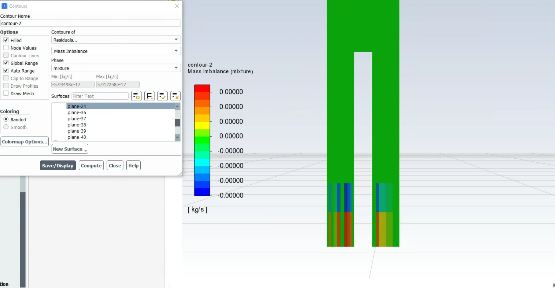
Forum ModeratorHave a look at the flow field too, ie velocity and pressure. There’s also a mass imbalance in the Residuals contour group, plot that. If Fluent is struggling to converge the mass balance tends to suffer, if you have a multiphase model on the lost/gained mass may not be the phase you expect. Note, you're only just getting vapour so it's a very small value that you're picking up too.
-
December 6, 2023 at 11:45 am
Diogo Martinho
SubscriberHey Rob,
Thanks for your answer.
I’ve checked the mass balance but it doesn’t seem to be the issue here.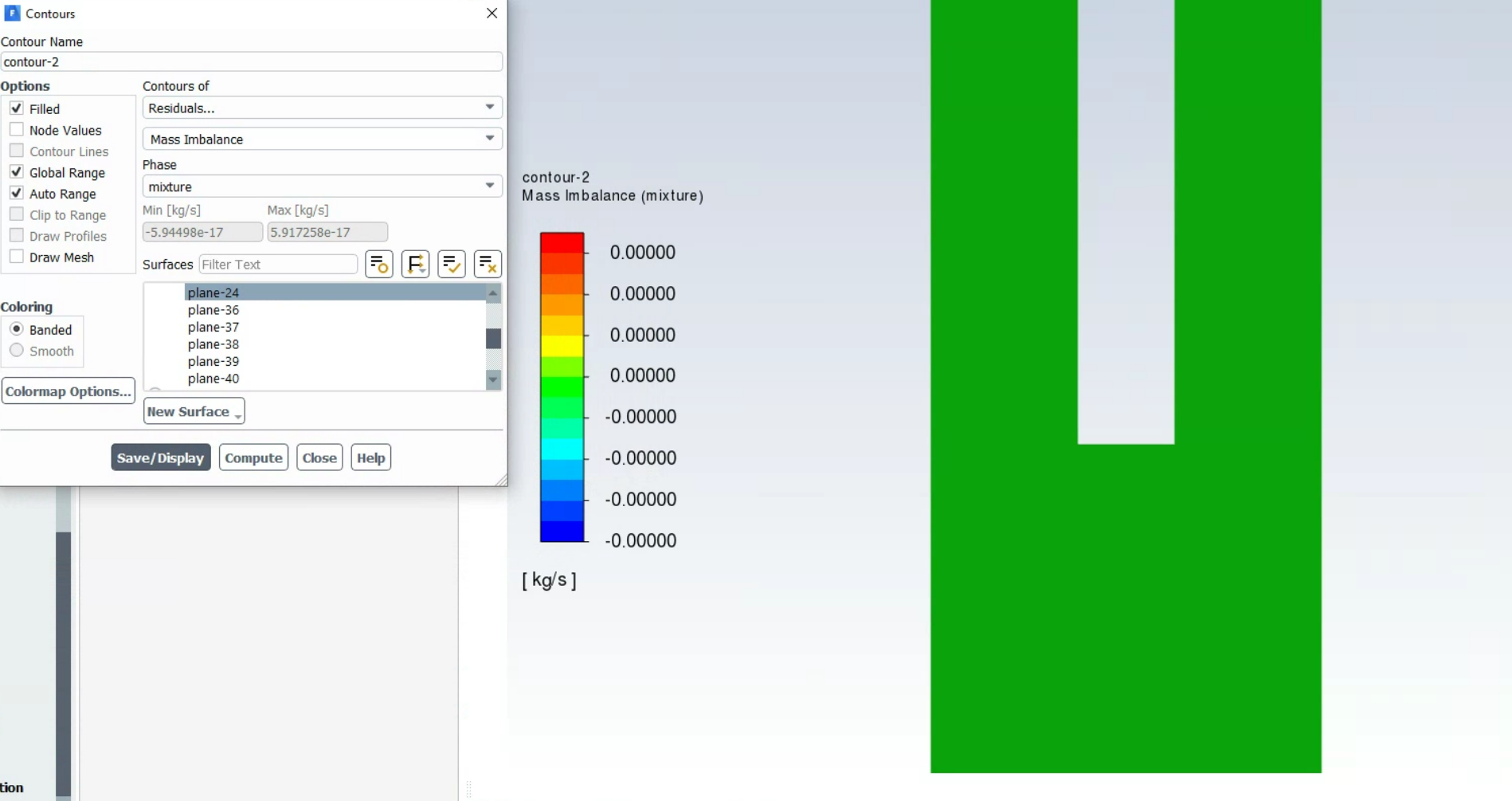
The reason why I am trying to get rid of that gas there, it’s because as soon as I start to add mass transfer from liquid to gas on the neighbour nodes (domains on the left and right), those nodes will have a huge amount of gas when compared to the nodes where the mass and momentum source terms are being added, and I believe that is a problem to have a convergence at the end.
I have also tried to define a low permeability to the gas phase there so it couldn’t go in, as if a "wall" was there to the gas phase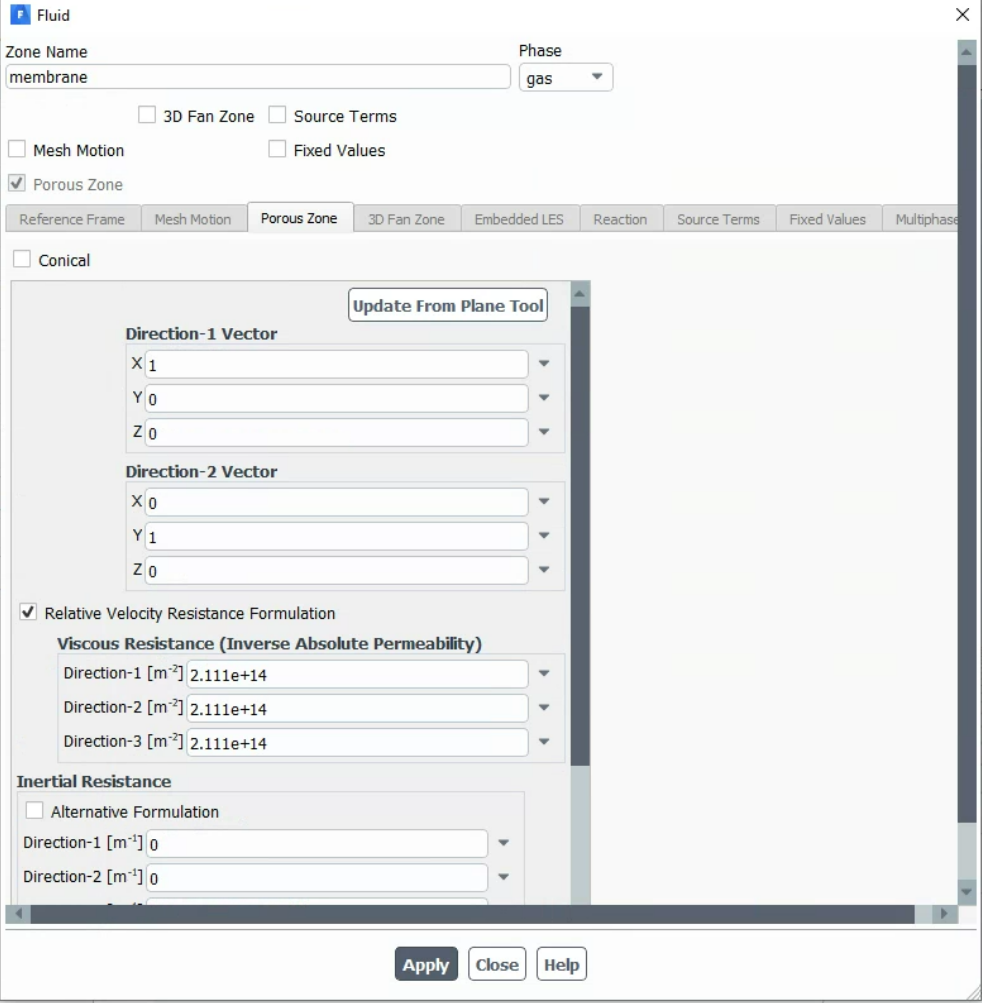
-
December 6, 2023 at 12:10 pm
Rob
Forum ModeratorHow is the convergence looking? How did you choose those porous coefficients? Velocity field?
-
December 6, 2023 at 12:38 pm
Diogo Martinho
SubscriberThe convergence looks okay, I let it run until the residuals are lower than e-7 only because I am tracking other parameters that are still converging though.
The value 2.111e+14 was just defined without any physical meaning. Just to ensure a high resistance to the gas phase in the middle domain.
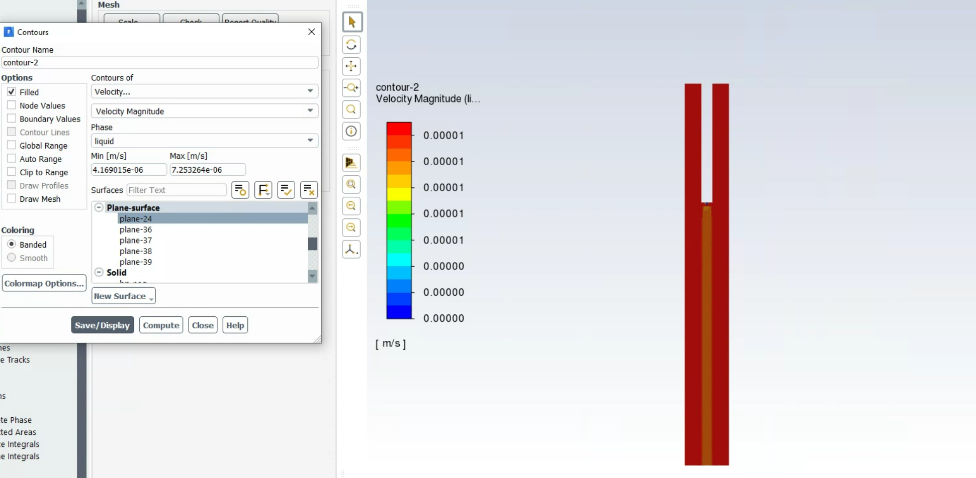
Velocity field looks like this (if I run the model without gas fraction)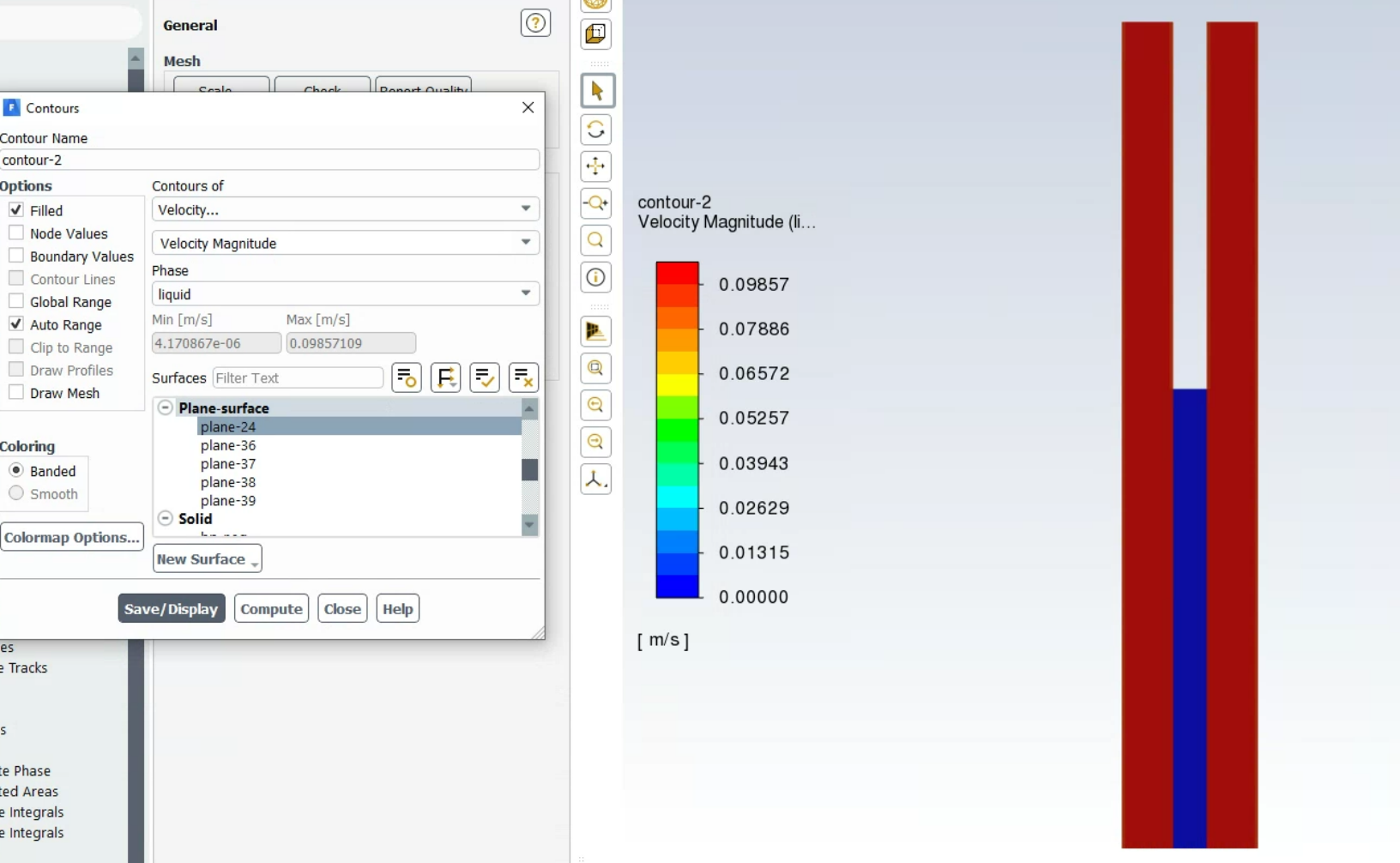
And like this when defining gas fraction of 1e-6 at the inlets
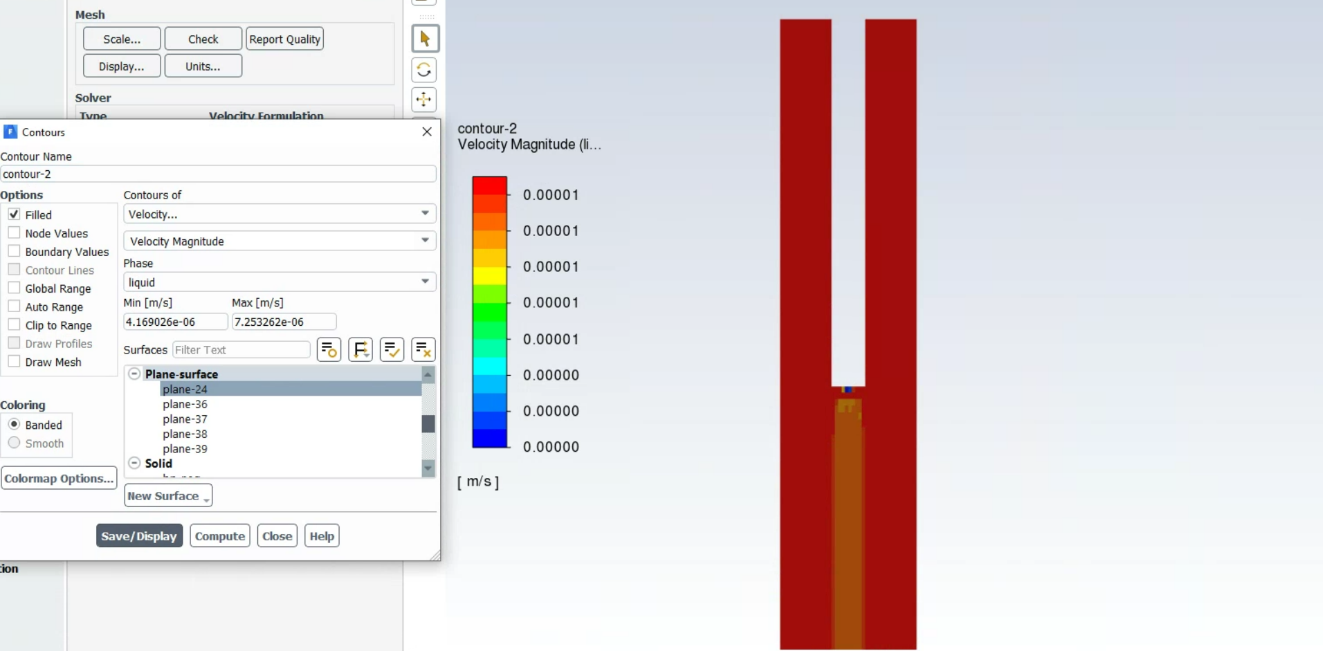
-
-
December 6, 2023 at 1:37 pm
Rob
Forum ModeratorOK, those values are quite high, so work them out properly. Look at the velocity & pressure gradients in detail in that region, I suspect you're stressing the numerical schemes with the sudden jump in velocity and flow resistance just next to a wall.
-
December 6, 2023 at 1:58 pm
Diogo Martinho
SubscriberI agree they are quite high ????. However, the three domains are porous domains, so, I have (from the left to the right):
CellRegion 1 and 3:
porosity = 0.38
liquid phase:
perm(x,y,z) = 1.216e-10
gas phase:
perm(x,y,z) = 1.216e-10
CellRegion 2:
porosity = 0.53
liquid phase:
perm(x) = 1.216e-10
perm(y,z) = 1.216e+14
gas phase:
perm(x,y,z) = 1.216e+14
My goal is that the liquid can only pass the centered domain on the x-direction and no gas can pass from the sides to the center, so that the centered domain would be impermeable to gases.
Am I thinking correctly or would you define differently?Thank you for your inputs btw!!!
-
-
December 6, 2023 at 4:12 pm
Rob
Forum ModeratorYou'll always get some of the wrong phase due to diffusion. I rarely go over a 1,000 or so greater for the coefficients if I want to discourage flow in certain directions, so for Direction 1, 2, 3 I might use 0.01, 0.01, 100 and adjust from there. This assumes the blocked fluid has somewhere to go.
-
December 6, 2023 at 5:01 pm
Diogo Martinho
SubscriberOkay, but the permeability 1.216e-10 is from the literature for those specific domains, then my "problem" is that 1.216e-10 is value for the lowest resistance in my domain.
What you are saying is that I should just try to change/increase by one or two orders of magnitude? Or those were raw values?
-
-
December 6, 2023 at 5:05 pm
Rob
Forum ModeratorDouble check what those values mean in the Fluent model. As I have no idea what you're doing I can't comment. For an open region I'd just leave the porous model off.
-
- The topic ‘(non-expected) gas fraction in cells near a wall’ is closed to new replies.


-
5094
-
1830
-
1387
-
1248
-
1021

© 2026 Copyright ANSYS, Inc. All rights reserved.

