TAGGED: -Ansys-Maxwell-electronics
-
-
December 5, 2023 at 8:45 am
Juefei Li
SubscriberHi community. I am working on a project about fault detection. I build a model of variable reluctance type wheel speed transducer in Maxwell, and inject some types of fault by changing the geometry of the original model. By running analysis, I can obtain the induced voltage in the coils. Then, I need to send the voltage information to MATLAB where I run the diagnose algorithm.
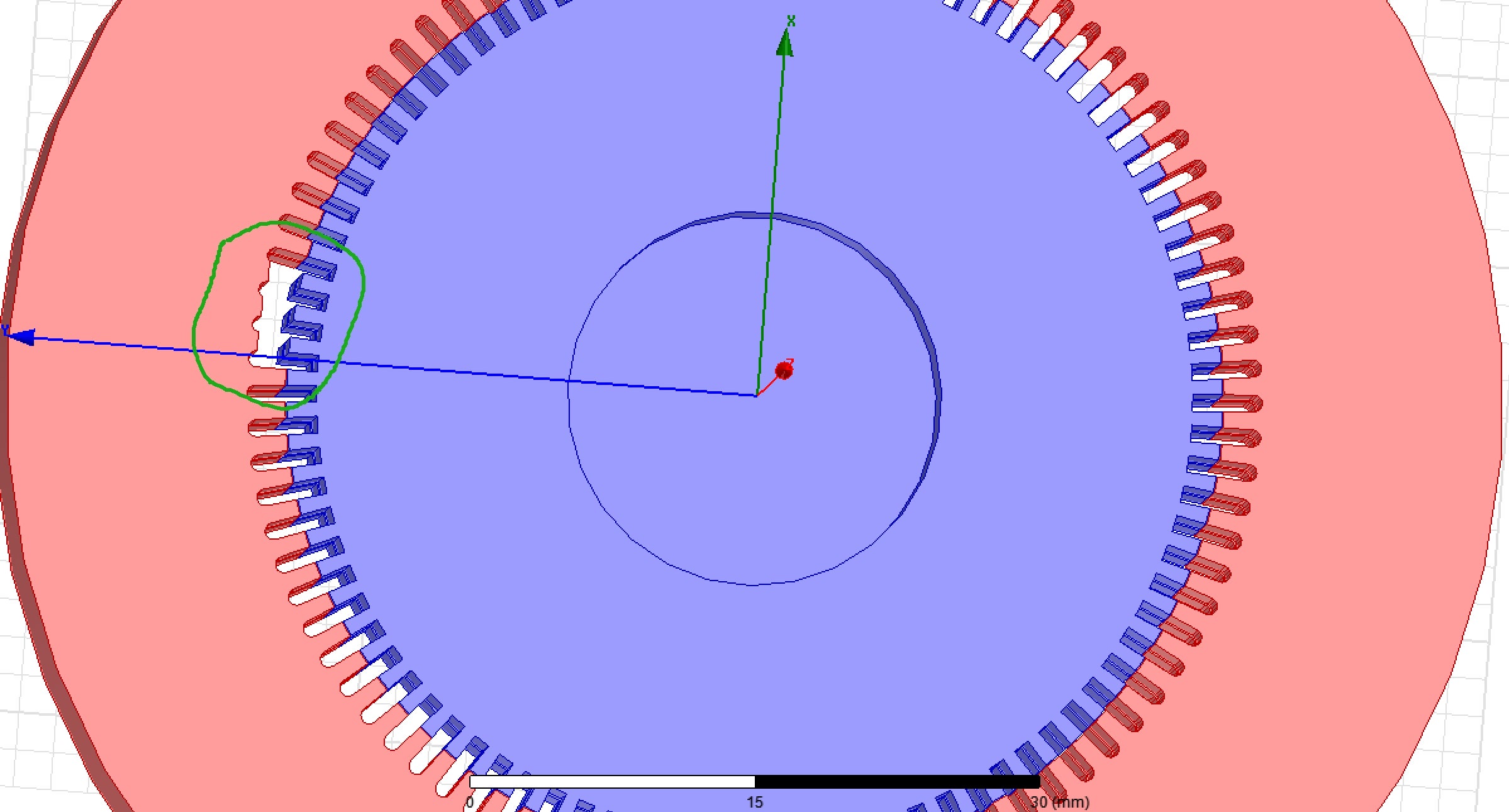
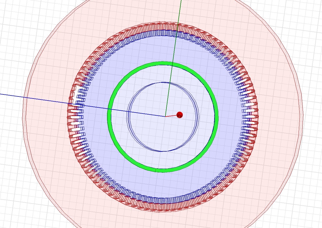
There are two problems now...1. Since I need to add motion to the model (like a rotational speed of 500 rpm), the 3D simulation of the complete model is too complicated and time consuming. My idea is to simulate only a part of it. This works well with the "healthy" transducer model, but the ones with faults are asymmetric. For instance, some teeth are broken (as shown in the figure), so the whole model is asymmetric. How to run simulation faster in this case?

2. I wanna realize real-time diagnose but I don't know how. It's like for the first 5 seconds, it operates normally; at 5s, a fault suddenly occurs. During this process, the induced voltage is transmitted into MATLAB simultaneously, so the diagnose result can change according to the real-time status. Is there any way to realize this kind of idea? I can't find any related materials...
Thanks a lot for your help. -
December 7, 2023 at 12:50 am
GLUO
Ansys EmployeeHello,
- I would suggest using a 2D model. Otherwise this model cannot be further simplified.
- This does not seem to be achieveable, Maxwell does not allow changing the geometry during the simulation.
GL
-
December 7, 2023 at 6:13 am
Juefei Li
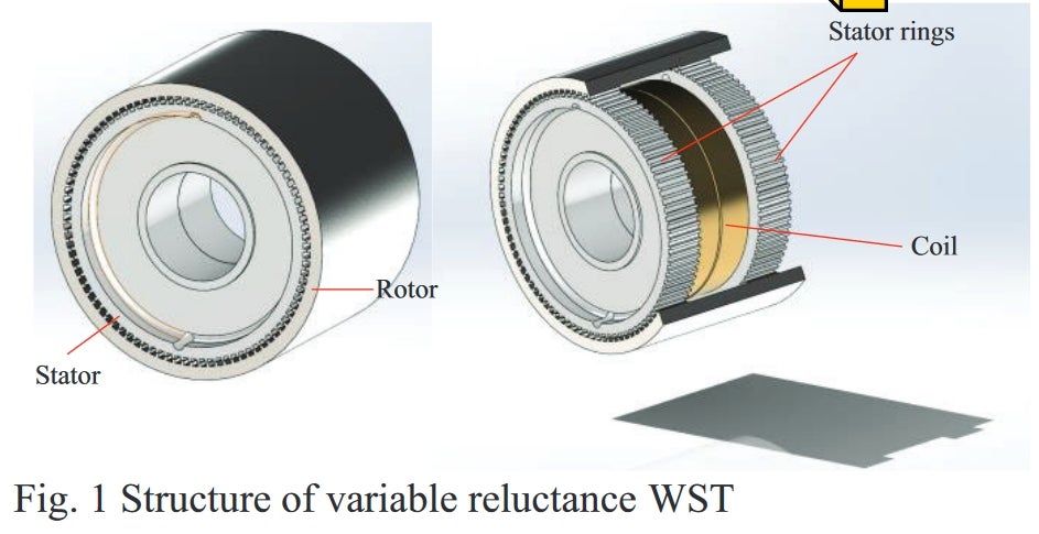
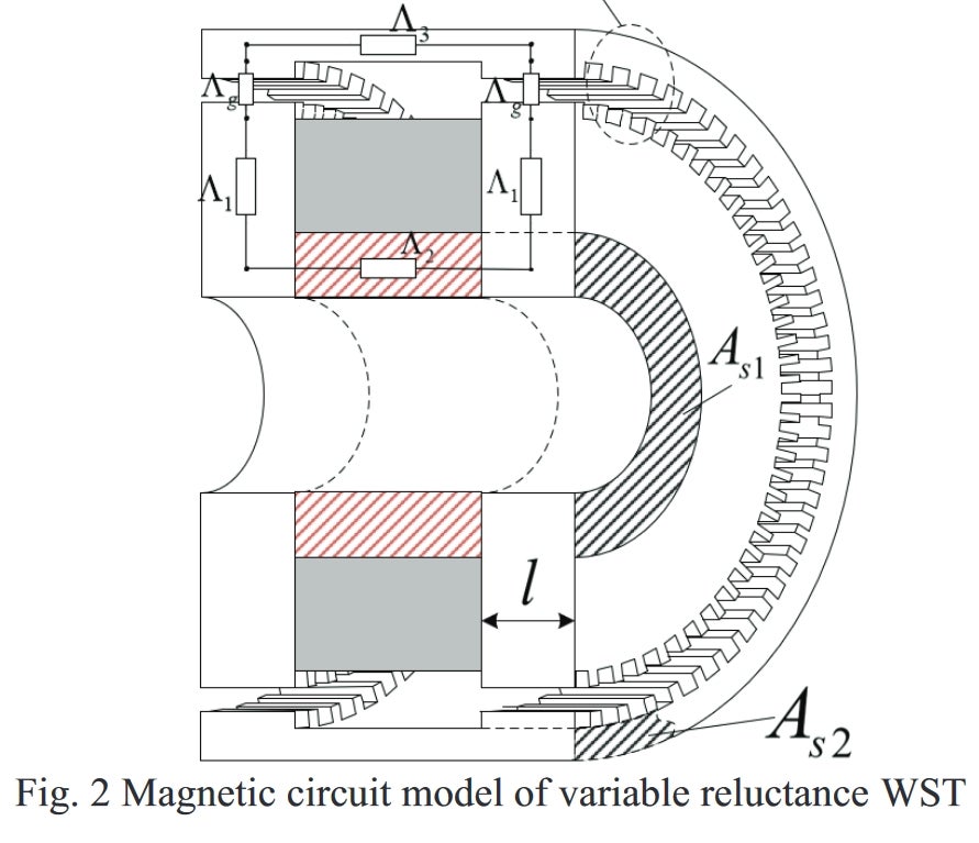
SubscriberThanks for your reply~ I'm new to Maxwell so I'm a bit confused about the scenarios in which I can use a 2D model. I asked a friend and he told me that I can't use 2D since my transducer has a 3D magnetic circuit... I've attached the structure of the transducer below. In Fig. 2, the red area is the permanent magnet, and the gray area is the coil window to pick up the signal generated by the rotor rotation. The magnetic circuit is shown in the upper part.
Could you please tell me when I can use a 2D model?
Many thanks!
-
December 7, 2023 at 6:40 pm
GLUO
Ansys EmployeeHi,
Yes, your friend is correct. I didn't see the coil there. 2D are only suitable for consistent geometry in depth or rotational.
GL
-
December 14, 2023 at 7:35 am
-
-
- The topic ‘Faster simulation for asymmetric model & Maxwell co-simulation with Matlab’ is closed to new replies.


-
4678
-
1565
-
1386
-
1242
-
1021

© 2025 Copyright ANSYS, Inc. All rights reserved.


