-
-
December 4, 2023 at 5:53 pm
imtiaz
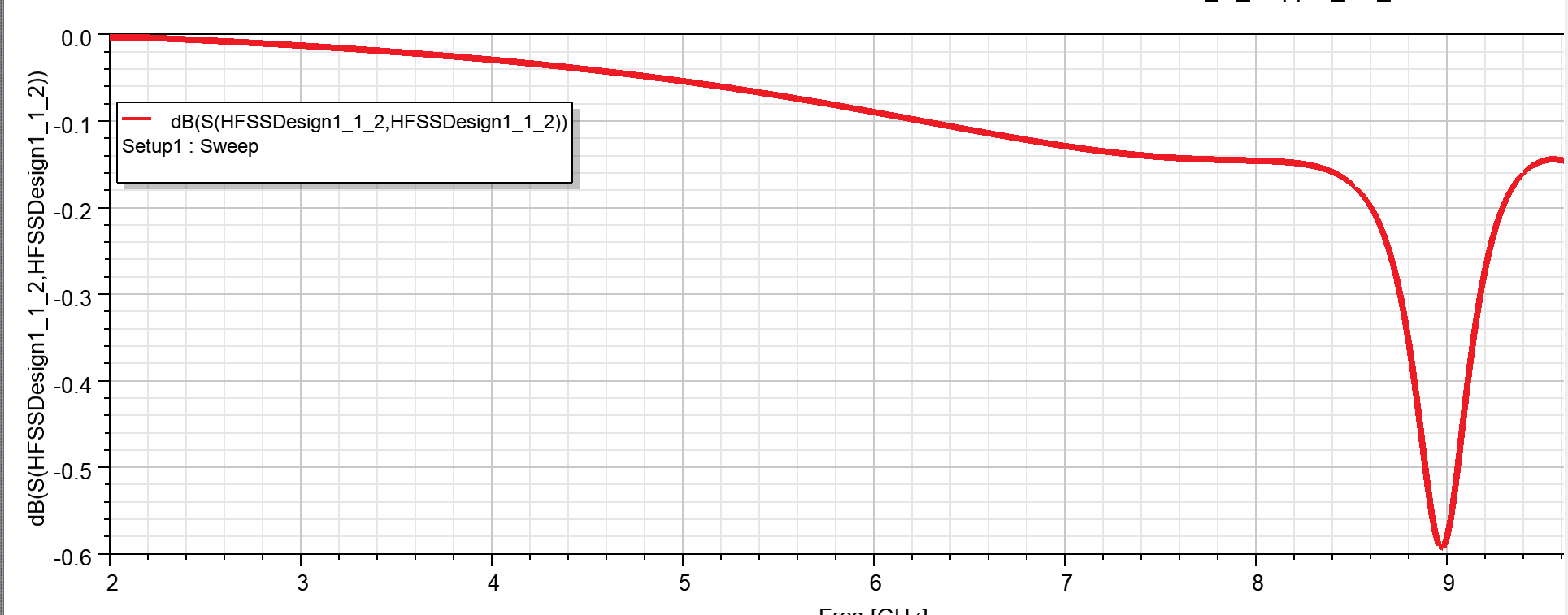
SubscriberWhen I used an SMA connector instead of a hfss port (lumped/wave), it returned an incorrect s11 (see attached image). Everything is fine because the pin is properly connected to the antenna's feed line.But why it is showing this type of behavior?
Are there any additional things need to do when I try with a SMA Connector model?
-
December 6, 2023 at 5:29 am
Praneeth
Ansys EmployeeHi Imtiaz,
It looks like there is an issue with the model. It looks like the signal is completely reflected back to the port. Please check the following in your model with the connector:
- Did you make sure that the connector outer conductor is only touching the ground planes?
- Did you make sure that the connector inner conductor is only touching the signal trace?
- Did you verify the port excitation on the SMA connector?
- Is there an explicit air region or how did you model the surrounding region?
- Are the dimensions for the SMA connector correct?
Best regards,
Praneeth.
-
Viewing 1 reply thread
- The topic ‘HFSS Port vs SMA Connector in Design – Provide wrong S11, Why?’ is closed to new replies.
Ansys Innovation Space


Trending discussions


Top Contributors


-
3777
-
1388
-
1188
-
1090
-
1015
Top Rated Tags


© 2025 Copyright ANSYS, Inc. All rights reserved.
Ansys does not support the usage of unauthorized Ansys software. Please visit www.ansys.com to obtain an official distribution.


