-
-
January 1, 2019 at 12:58 pm
Jamessmp23
Subscriber
Hello all,
1) I would like to know. Why the water velocity goes out of the drawing geometry ?
2) Why the vector velocities are not symmetric in the top of riser ? is it because of transient solver ?
Â
Information : 2D, transient solver, Euler multiphase model, k-epsilon realizable. Hybrid initialization, patching air volume fraction = 0.5
Best regards,
James
Â
-
January 1, 2019 at 1:09 pm
raul.raghav
SubscriberJames,
Is it a 2D or 3D case? And have you checked the volume fraction contour after you've patched the air volume fraction? Can you attach the volume fraction contour?
-
January 1, 2019 at 3:24 pm
Jamessmp23
SubscriberThanks Rahul,
it is a 2D case, I already check for volume patching.
I had tried without patching and result was air did not flow into the reactor for the volume contour.
regards,
James
-
January 1, 2019 at 3:36 pm
raul.raghav
SubscriberCan you attach a screenshot of the contour? And can you provide a simple schematic of your model specifying the inlet and outlet boundary condition showing how the phases are distributed.
-
January 2, 2019 at 2:23 am
-
January 2, 2019 at 10:40 am
Jamessmp23
SubscriberThe inlet BC is 0.75 m/s for air velocity magnitude, volume fraction =0. (at the phase air diameter = 5 mm), for outlet BC I desire to have the ambient pressure, for my thought, it is already setup as 1 atm at the outlet pressure.
I had tried to modified the vector plot but it still goes out of the geometry. For my though, the water might flow upward and then fall down. if it's not correct please inform me. About the symmetric, How to set it up using the planar solver ? For my understanding its depends on the input parameters ex. bubble size,.Â
please inform me,am I understand it correct or not ?
Best,
James
-
January 2, 2019 at 11:34 am
Rob
Forum ModeratorThe flow around the base looks sensible. The vector is scaled by the velocity (usually) and it's starting point is the cell centre. In models with a range of velocity it's common for faster moving regions to have vectors that are larger than the cells: this is why you have vectors sticking out of the domain. What it means is that at the cell centre the flow is travelling in that direction and if you refine the mesh you'll (eventually) see the turning effect.Â
I don't know why you've got the high velocity region at the top, is there a boundary condition change in the corner? It could also a poorly converged result.Â
-
January 2, 2019 at 1:22 pm
Jamessmp23
SubscriberThank you for the advice, I will try to refine the mesh and simulate again.Â
There is no change in the boundary condition, I only input the air magnitude in the inlet boundary and set others into walls and outlet pressure.
regards,
James -
January 2, 2019 at 4:40 pm
Rob
Forum ModeratorWhere is the outlet?Â
-
January 3, 2019 at 1:09 am
Jamessmp23
SubscriberThe outlet is the outlet pressure at the top. In this case the outlet is only air, water is circulate in the reactor.Â
regards,
James
-
- The topic ‘
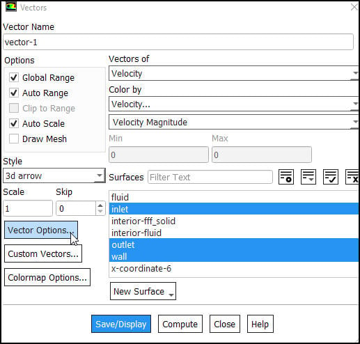
Vector velocity plot goes out of the drawing geometry’ is closed to new replies.
-
4979
-
1650
-
1386
-
1242
-
1021
© 2026 Copyright ANSYS, Inc. All rights reserved.


