I would like to ask a theoretical question regarding contact debonding for cohesive zone model (CZM) (Mode-II) based on Separation-distance based debonding. I carried out a simulation in static structural and have a confusion for which I request guidance from experts.
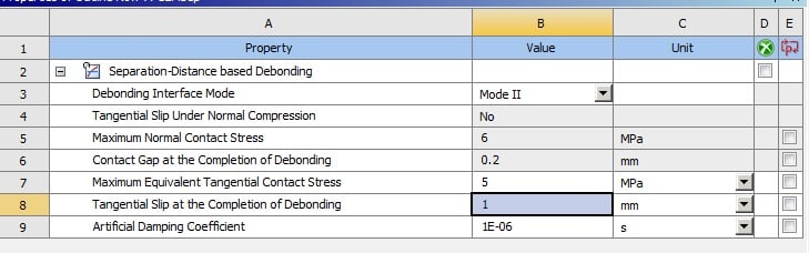
For the above mentioned Mode-II CZM,in Ansys workbench the required input values are as following,
1. "Maximum Equivalent Tangential Contact Stress (say in MPa)" From here-on mentioned as C3.
2. "Tangential Slip at the Completion of Debonding (say in mm)" From here-on mentioned as C4.
3. "Artificial Damping Coefficient" (say in sec) From here-on mentioned as C5.
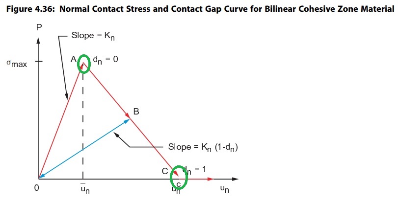
I checked the Ansys theoretical manual and from the manual the above mentioned input parameters (C3 and C4) are marked as green circles in the graph below. (for discussion let's call it Fig#1)
My questions are,
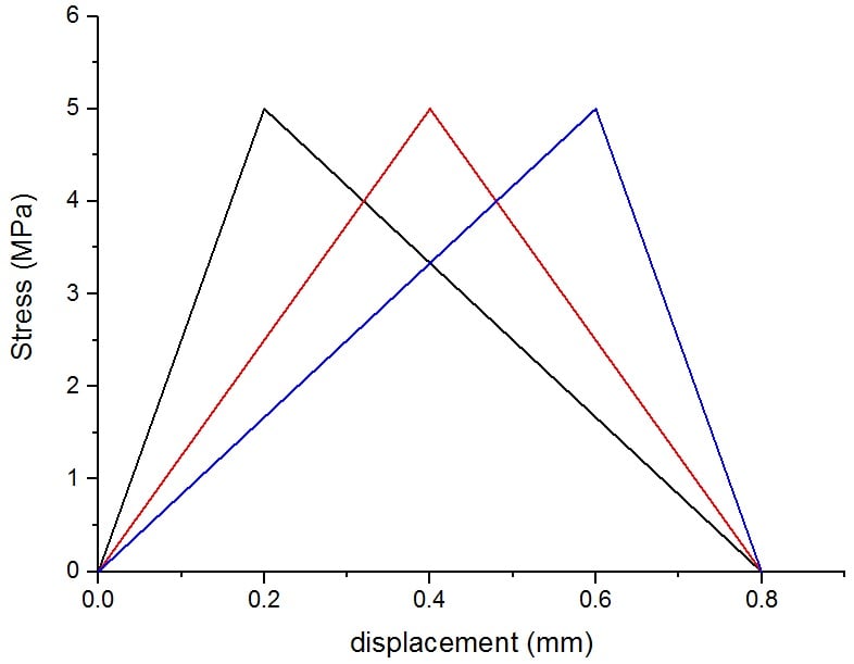
(a). If I input the above mentioned parameters for CZM (i.e. C3,C4,C5) then how does the Ansys solver differentiates between the following curves? The values for the following curves are imaginary which I made up to ask my confusion. In the curves below, all of the curves have same C3 and C4 values but the corresponding displacement or slip value of C3 are different. Noting that in Mode-II CZM we can only input the C3 and C4 and not the corresponding slip of C3. (for discussion let's call it Fig#2)
(b). If the answer to the previous question is because of slope (or initial gradient or stiffness), then could some one may clarify the following question. I input the following commands in my pull-out contact debonding model to modify the contact stiffness.
rmod,cid,3, -59.453
rmod,cid,11, -59.453
I ran the simulation with different values of stiffness but with the same CZM input values (C3,C4 and C5) and with same analysis settings and boundary conditions. I recorded the force reaction, slip and frictional stress, and plotted the results as shown below, (for discussion let's call it Fig#3 & Fig#4)
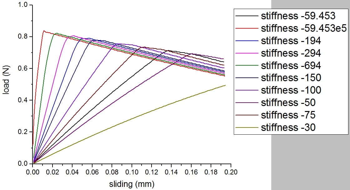
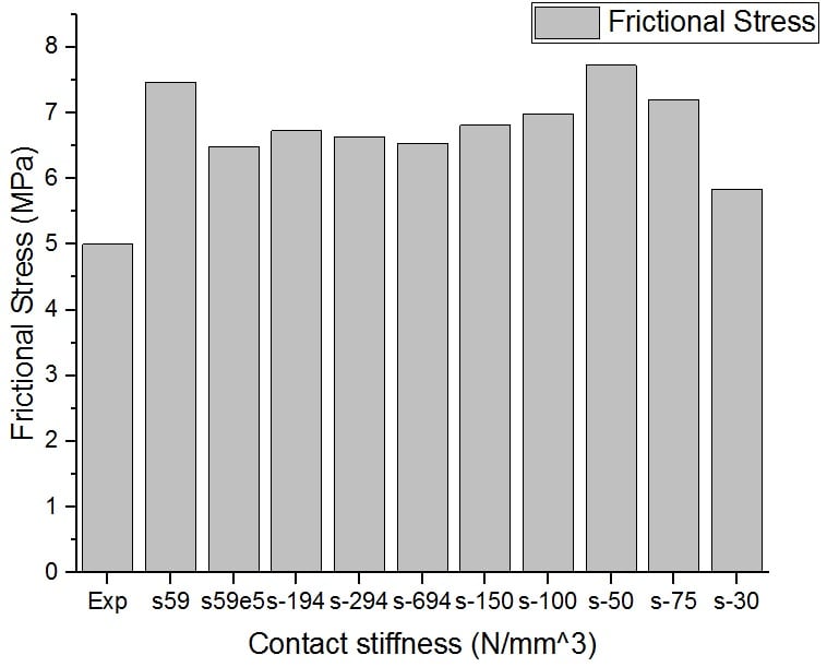
(b-i) why with the lower stiffness values, the load is also decreasing provided I did not change the CZM input values?
(b-ii) Shouldn't be with the same C3 and C4 values and with different stiffness I shall get the curve as shown in previous image above Fig#2?
(b-iii) Could someone please specify the issue and guide me how could I get the resultant values so that the hypothesis/theory mentioned above for Fig#2 could be verified/checked in Ansys simulation.
(b-iv) why do we use negative sign in defining the stiffness value via APDL command? I found these at here.
Thank you


