-
-
November 25, 2023 at 1:17 pm
sagar
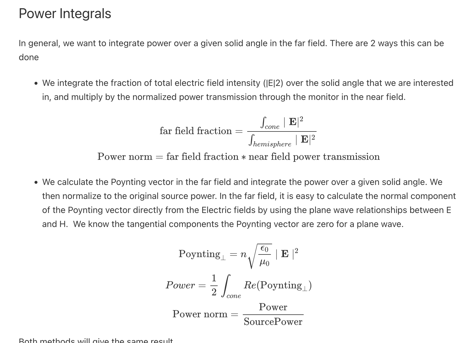
SubscriberTo calculate the fraction of power emitted in the forward or backward direction we use a transmission monitor just the top or bottom of the structure, where the electric dipole is situated inside the metastructure. Then by projecting them into a far field, we can calculate the electric field intensity in the far field on a sphere. We are taking a rectangular monitor for the calculation and the monitor has a finite size and is placed some finite distance from the metastructure, which is associated with some collection angle less than 90 degrees. By projecting them into a sphere (including the forward and backward monitors) eventually, we can get total emission in both directions, which will not be equal to the dipole power, as in each case we have taken some solid angle less than 90 degrees and missed the information of some angle. How to resolve this issue where I can truly calculate the total emission in forward direction (from 0 to pi) and backward emission (from pi to 2pi)?
And the way the integrated power calculation is shown here will work for a plane wave source but as we are working with an electric dipole source which has a certain angular spread in radiation, how will it be modified?
-
January 8, 2024 at 10:57 pm
Amrita Pati
Ansys EmployeeHi Sagar,
We found this post was unaswered for a really long time. I thought we had replied to a similar post but I suppose not. I sincerely apologize for this. As far as I remember, you couldn't use box monitors because they have to be placed in a homogenous medium. You are correct that you will miss a certain amount of power because of the use of planar monitors. Unfortunately, there is no other way to acheive this. You can make the monitors extremely large in the transverse direction to capture most of the power (so that a larger section of the fields that will eventually propagate to the far field can be recorded) but at the end of the day you won't be able to account for some. You may compensate with the size by keeping the monitors closer to the source.You can refer to the following article and the associated script for farfield power integration calculation: FDTD vs stackdipole - halfspace emission in a multilayer stack.
Regards,
Amrita
-
- The topic ‘Emitted power calculation from a electric dipole through transmission minitor’ is closed to new replies.


-
4673
-
1565
-
1386
-
1231
-
1021

© 2025 Copyright ANSYS, Inc. All rights reserved.


