TAGGED: ductile, fea, mechanical, metal, stainless-steel, steel
-
-
November 18, 2023 at 10:05 pm
Georgios Panagiotopoulos
SubscriberHi everyone,
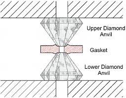
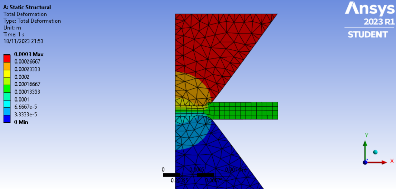
I am trying to run an FEA for my Masters Project, where I am compressing a steel gasket (thin sheet of metal) between two diamonds. The compression of the gasket should create a sort of bulge of the metal as shown in the first figure. For some reason this bulge is not appearing in my simulation (second figure). Any ideas why?
-
November 20, 2023 at 2:04 pm
Armin
Ansys EmployeeHi Georgios,
Please check the following items:
- Check the contact between the gasket and the diamond. From the picture, it appears that a small interference is present in the results.
- Reduce the mesh size, particularly for the gasket. Capturing the bulge may require a finer mesh.
- Make sure proper boundary conditions are applied to the gasket, specifically for the free end of the gasket that may influence the resulting deformation field.
-
November 20, 2023 at 4:13 pm
Georgios Panagiotopoulos
SubscriberHi Armin,
Thank you very much for your advice!
I have refined the mesh and fixed the contact so that the intereference no longer occurs, but the bulge is still not showing. My only boundary conditions are displacement at the top of the top diamond and a fixed support at the bottom of the bottom diamond. Do you think they need to be adjusted?
George
-
November 20, 2023 at 4:41 pm
Armin
Ansys EmployeeNo problem Georgios.
Are you sure that the bulge forms in an actual situation? The picture that you provided seems like a schematic rather than an actual experiment. But if the bulge is expected to form, you may adjust the friction coefficient between the diamond and the gasket (while keep using a fine mesh), as well as adjusting the boundary conditions at the free end of the gasket that may be switched to a fixed support, for example.
Also, if you're using metal plasticity, you may check how the associated plasticity parameters can influence the results.
-
November 20, 2023 at 10:58 pm
Georgios Panagiotopoulos
SubscriberHi Armin,
Yes, the bulge also occurs in experiments. I tested out many different friction coefficients, but that also did not solve the problem. I tried different boundary conditions and none of them resulted in a bulge, just the gasket tilting upwards. How can the plasticity parameters be changed? I am using the default stainless steel for the gasket. Thanks again!
-
November 21, 2023 at 3:01 pm
Armin
Ansys EmployeeHi Georgios,
For more information about plasticity models, you can check the free course below in Ansys Innovation Space:
Topics in Metal Plasticity | Ansys Innovation Courses -
November 22, 2023 at 4:34 pm
Georgios Panagiotopoulos
Subscriber -
November 22, 2023 at 5:09 pm
Armin
Ansys EmployeeHi Georgios,
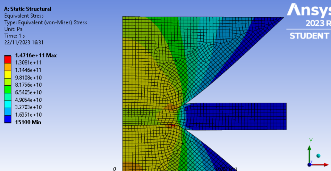
The stress distribution looks file to me. Around the fillets is where we typically see larger stresses. I suppose you used plasticity in the gasket.
By the way, you can specify the diamonds to behave like a "rigid" material since they are much stiffer than the gasket and I assume stresses in the diamonds are not of importance. This will significantly reduce the run-time of the model. Just a suggestion.
-
- The topic ‘Metal Bulge’ is closed to new replies.


-
5059
-
1764
-
1387
-
1248
-
1021

© 2026 Copyright ANSYS, Inc. All rights reserved.


