-
-
November 29, 2018 at 11:46 am
fx213
SubscriberHello,
I tried to set up a static analysis for a compression test on a part of a model in ANSYS Mechanical, after I had determined the properties, through test data input, in Engineering data. The model consists of two materials, steel and rubber.
After I selected the loads and constraints to be applied and after that to Solve the analysis to get the relevant results, on the right side dialog appeared the notification to 'Verify material'.
Thus, I would like to make a query on which cases the materials of a model do not be defined in Engineering data in ANSYS W/B.
Thank you.
-
November 29, 2018 at 12:40 pm
peteroznewman
SubscriberHello fx,
Please open Engineering Data from the Static Structural model in Workbench. Click on the rubber material, and save a screen snapshot of the details of the rubber properties and insert that image file into your reply. Did you select a material from the library? Which one? What version of ANSYS are you using?
Is Invalid Geometry an appropriate title for this discussion? Perhaps you could edit the title to say Verify Material or something similar.
Regards,
Peter -
November 29, 2018 at 4:40 pm
fx213
SubscriberDear Peter,
I selected structural steel for the one material from the library, however I determined a new material for rubber (hyper-elastic epdm in screenshot).
I am using ANSYS 18.0. version of the software.
I gave this discussion title as I assumed that are related topics. From preview of the results, in comments section that appeared when something is not correct in the analysis, was indicated this message ('Invalid geometry') along with the notification in blue letters 'Verify material' on the right side of the dialog.
I also tried to select, through right-click on each one of the parts of the model (Analysis tree), to select 'Insert', in the event that I could assign the material in that way. There was no active option for something like that.
Thank you in advance for any help you can provide me.
Kind regards,
FXanthaki
-
November 29, 2018 at 6:24 pm
peteroznewman
SubscriberDear Xanthaki,
You must fill out fields in yellow so ANSYS has the sufficient and correct data to proceed. Provide a Temperature. Uniaxial test data is a Tensile test, so the strain must be positive. You usually have many data points in the Experimental table, not just one. Link to example.
Experimental Test Data such as Uniaxial is provided as a place to hold the data which is used in a Curve Fit operation that determines Parameters for a Hyperelastic Material Model.
You learned some of this in a previous discussion.
Please reply with more information on the experimental data that you have.
Regards,
Peter
-
November 30, 2018 at 11:51 am
fx213
SubscriberDear Peter,
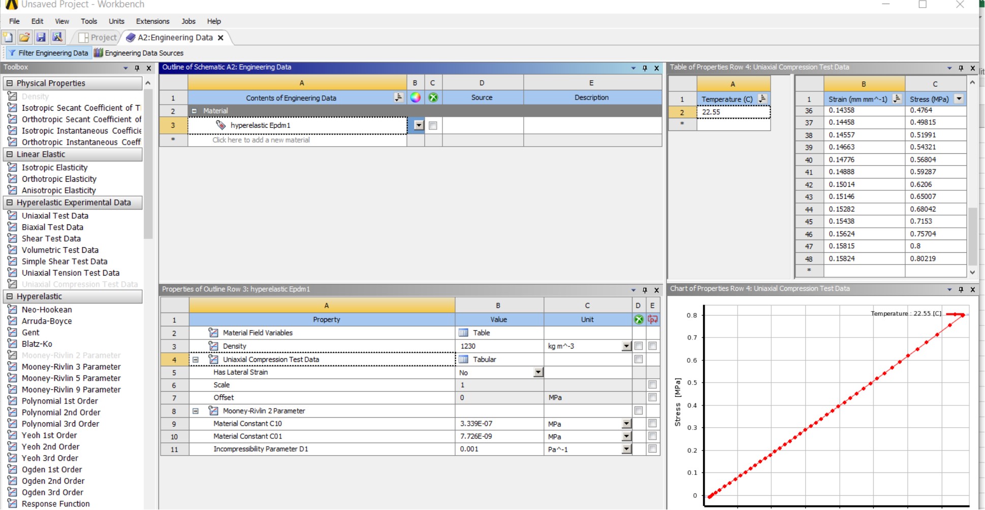
I provided temperature and more data than before, which are the measurement values of the unloading of a cycle in my test (Image 1). It is about a compression stress test by the way, it is not a tensile one. Thus, I selected the Uniaxial Compression Test Data.
Concerning the experimental test data and Curve Fitting operation you referred to, that determine the Parameter for a Hyper-elastic material Model,
I had tried to input the stress- strain data I have in Compression tests Data again, and selected Mooney-Rivlin Parameter 2. I chose the Curve Fitting option and the right-click 'Solve the Fit' from that drop-down menu. It did calculated the coefficients (material coefficients, C10, C01) of the model. However, the three curves of uniaxial, biaxial and shear deformation modes do not appeared in one graph, after the Curve Fitting selection of the model, as I have been advised from an ANSYS tutorial on this specific issue. I am not confident why this happens (Image 3).
On the contrary, when filling in the coefficient constant C10, C01 with values I have found in literature (C10, C01 coefficients from experimental studies in literature), the three curves of uniaxial, biaxial and shear do appeared in the graph (in blue, red and green lines)(Image 2),as shown in the relevant tutorial as well.
At the third image you can find attached, it is one of my trial, choosing another hyper-elastic material model (Neo-Hookean) with input of stress-strain Test Data again of compression test, and using the Curve Fitting operation (right-click on Neo-Hookean cell line). As you can see, it is only the shear modulus dotted curve that appeared when the Neo-Hookean cell line is selected.
What I want to do next, is to ensure that these material & properties I have determined as properties in the Engineering data is saved and defined for the parts of the model I need to run the study for, so as to be able to go ahead to defining the Analysis Settings for the set-up. This is my problem, because when I click on the analysis tree, no material seems to be selected.
Thank you in advance for any help you could provide me.
Kind regards,
FXanthaki
-
November 30, 2018 at 12:43 pm
peteroznewman
SubscriberDear Xanthaki,
The benefit of hyperelastic material models is to handle the very nonlinear behavior of materials at very high levels of strain.
The stress-strain curve you show in the first image above is a straight line out to the last point at about 0.15 strain. If your model does not need to go past that value of strain, I suggest you take the slope of that line and create a linear elastic material with that Young's Modulus. That simple material model will capture all the behavior in your experimental data.
Hyperelastic material model might help if you have convergence difficulties in your model, but see what you get with a linear elastic material first.
I invite other members of the community to comment.
Regards,
Peter
-
- The topic ‘Invalid geometry’ is closed to new replies.
-
3029
-
971
-
858
-
836
-
777
© 2025 Copyright ANSYS, Inc. All rights reserved.