-
-
November 11, 2023 at 5:53 pm
ANSYS EXPLORER
SubscriberDear Experts,
I am performing a coupled Analysis, Steady state thermal followed by Static structural analysis using ANSYS workbench - 2023 R2 version. The FE model is having combination of a column and vessels connected together through nozzles and intent of analysis is to obtain the reaction loads due to thermal growth along with other static structural load like pressure, thrust and self-weight of the equipment at the nozzle / structural connections.
Boundary condition:
Column (center equipment) skirt is constrained at all x, y and z direction.
Vessels at both sides are mounted on the column by structural supports and connected through nozzles.
we used remote point and followed by remote displacement to fixed 6 DOF at where reaction is requested from FE model.
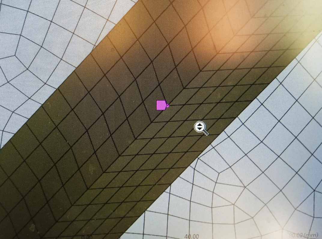
We used Solid elements, Quad mesh using shared topology with Symmetry model in ANSYS workbench and successfully import the temperature on the model. While running the static structural analysis, we get the following error and unable to complete the analysis further. Solution is interrupted.My understanding is since i used shared topology method , all mesh are connected together with out any contact (gap) issues, hence there should not be any chance for rigid body motion in the model.
Error message is as below:
"
An internal solution magnitude limit was exceeded. (Node Number 7677, Body Geom-2\Solid1, DOF UZ) Please check your Environment for inappropriate load values or insufficient supports. You may select the offending object and/or geometry via RMB on this warning in the Messages window. Please see the Troubleshooting Section of the Help System for more information."
Requesting your guidance to fix this error, as early as possible.
Thank you.
RegardsAE
-
November 11, 2023 at 6:44 pm
peteroznewman
SubscriberThough you used Shared Topology, there may be a piece of geometry that is not connected. A good way to find that piece is in Workbench, drag a Modal analysis out and drop it on the Model cell of your Static Structural model. In Mechanical, drag the Remote Displacement that supports the structure and drop it under the Modal analysis. Under Analysis Settings, increase the Number of Modes to find to 12. Solve, then look at the first 6 modes. If some modes are nearly zero, there is a part that is not connected. In the Details window, the part with the maximum displacement is the loose part. It helps if the geometry has been named in a way that makes it easy to identify. If not, you can see it by animating the displacement. Turn up the Result deformation scale factor until you see the part moving into view.
-
November 12, 2023 at 12:20 pm
ANSYS EXPLORER
SubscriberDear Peteroznewman,
Thank you for yiur swift reply.
I performed the modal analysis as suggested and found first 3 modes are equal to zero value. Surprised to see these modes are linked to main parts like shells and nozzle connections which are not having proper connectivity.
Marked up sketch which are having loose parts (3 Nos) from modal analysis attached. Then i took a action to connect these parts with adjoining parts using JOINT in workbench. But, No sucess, as it is not getting scoped with adjoining faces when we select the respective face ( reference face and mobile face) of component for JOINT. What could be the reason ?. Is it due to meshing with shared topology ? so i am not able to connect through JOINT?. Please advise the way out. Thank you.
Regards
AE
-
November 12, 2023 at 2:06 pm
peteroznewman
SubscriberIn SpaceClaim, remove the Shared Topology. Put the parts that need joints into separate Components.
In Mechanical, use Mesh Edit, Node Merge when nodes line up along a common edge. This is equivalent to the outcome of Shared Topology.
Use Bonded Contact, Behavior = MPC on edges where the nodes do not line up perfectly.
On edges where there is a significant gap, you should be able to use a Fixed Joint if the two sides are in different Components in SpaceClaim.
-
November 13, 2023 at 10:24 am
ANSYS EXPLORER
SubscriberDear Peteroznewman,
Since i went for shared topology, to overcome the “insufficient support” issues. But it seems the said method is not giving 100% result. So, i removed shared topology fully and i took the following steps.
- Meshed the FE model using Global and Local meshing.
- Checked the Initial Contact results.
- Found two set of components having “Far open” status as per contact results, then those i have connected with “fixed joint”.
- Run the complete FE model- thermal followed by static structural.
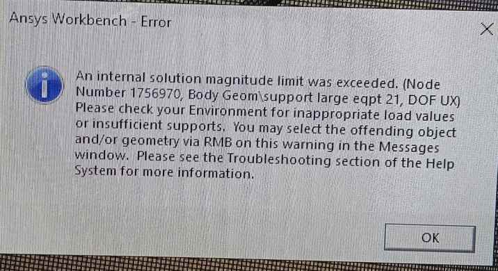
- I surprised to see the new error showing a signle node on “support” having “insufficient support”. Further, modal analysis results did not highlight this component as a loose part. I could not understand why this conflict result in workbench.
- The solution process is terminating at 87% of structural run with the below error.
- Please guide. Also i am not much fimilair to ” node merging “. Kindly eleborate. Thank you for your help.
-
November 13, 2023 at 11:00 am
-
November 13, 2023 at 10:14 pm
peteroznewman
SubscriberThe body is not connected. A single random node is called out on that body. There is nothing special about that node.
Use two bonded contacts, one on each end of that body to connect it to a face on an adjacent body. Use the Contact Tool to check the Initial Contact status.
-
November 14, 2023 at 2:20 am
ANSYS EXPLORER
SubscriberDear Peteroznewman,
Thank you for your response.
I have followed the suggestions as given in your message.
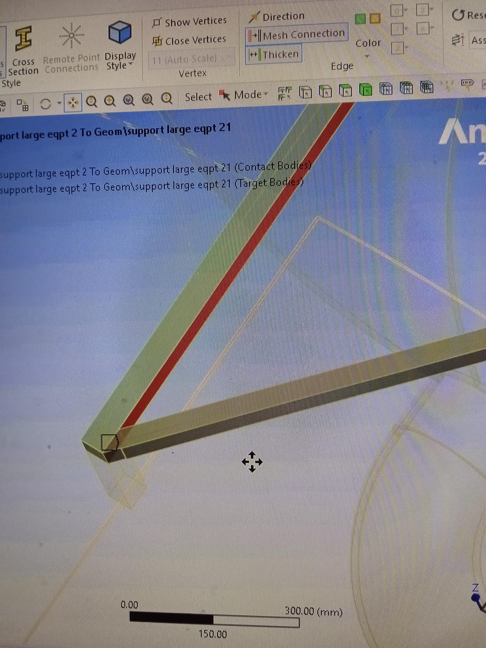
Bonded Contact estabished at one end:
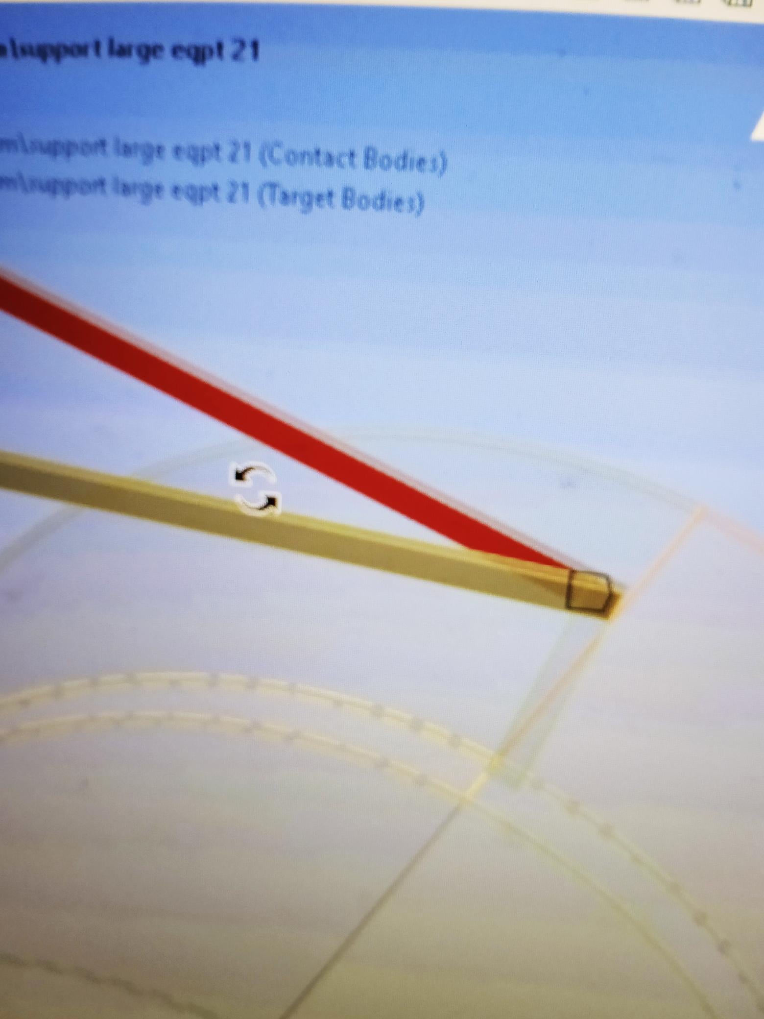
Bonded Contact estabished at another end:
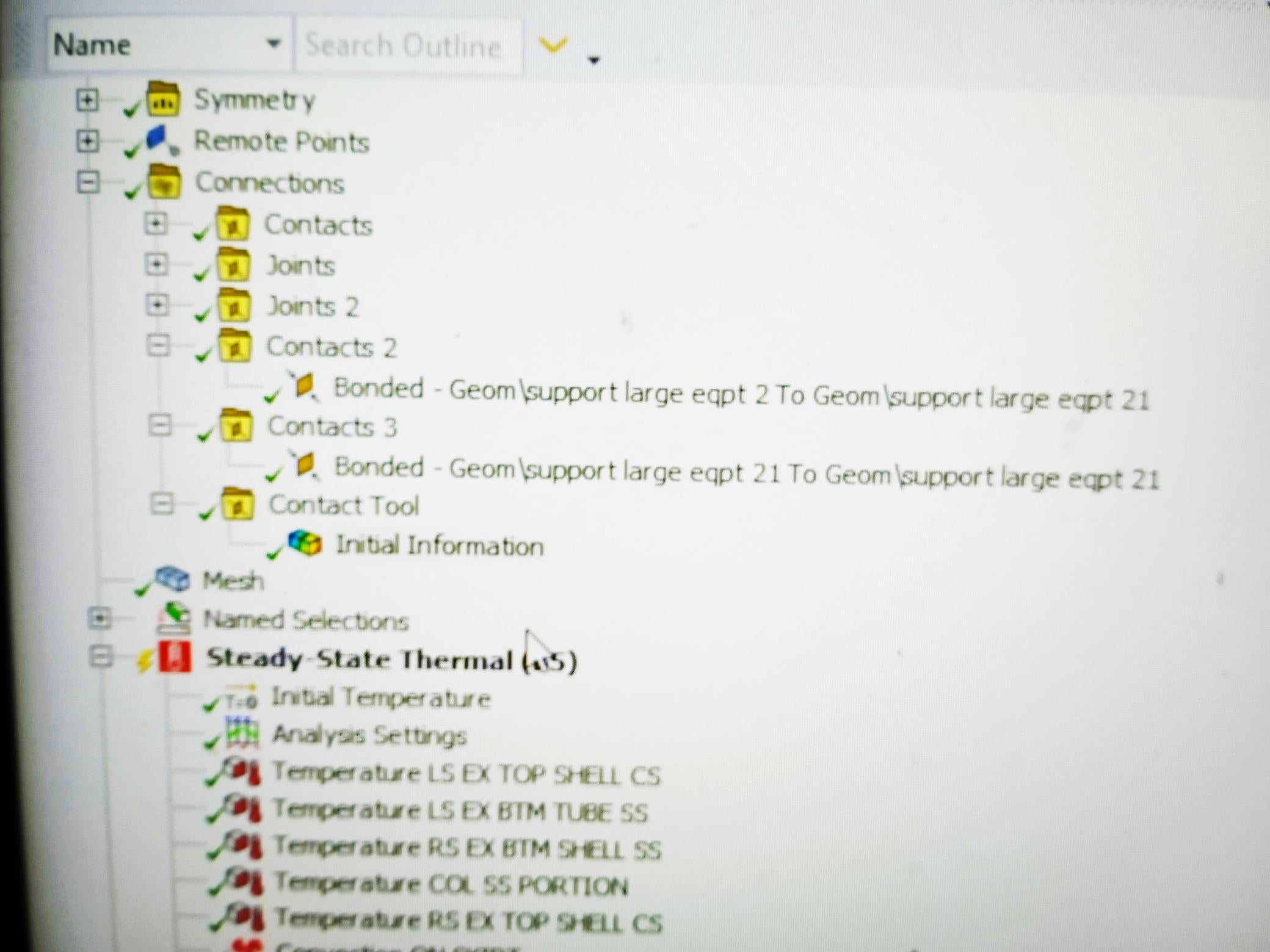
bonded contact initial result is succesfull as shwon in green tick as below.
When we run the model, it shows the same error at that same node (ID 1756970) and stopped solution processing at 87% of structural run.
I also tried with using of bonded contacts of different other faces of problematic body to it adjacent body. But No sucess.
Please help. Thank you once again for your support.
Regards
AE
-
November 14, 2023 at 5:28 am
ANSYS EXPLORER
SubscriberFuther, as you suggested , i took following steps in another effort.
- Freeze all mesh except problematic body (cross support). And meshed seperately with finer mesh using body sizing in that problematic body. Then joined using FIXED joint with adjacent bodies.
- But No sucess . The same error has come at 87% of run.
Please advise. Thank you.
-
November 14, 2023 at 2:05 pm
peteroznewman
SubscriberDuplicate the Static Structural analysis so you can try a different approach. Open the Geometry of the copied analysis in SpaceClaim and create lines along the beam-like supports. Try the 3D sketch tool. You will also need to create a Cross-Section for the beams and orient each beam in space. If you split the beam-like solids into extrudable shapes along the beam length, you can use the Convert button to automatically get beams and cross-sections. It will take some time to learn how to create beams, but this knowledge will be useful to have on many projects in the future.
The end node of the beam can be connected to a vertex or an edge on the surface bodies of the tanks using a Fixed Joint.
-
November 16, 2023 at 2:54 am
ANSYS EXPLORER
SubscriberDear Peteroznewman,
Thank you for your valuable guidance. Will take a note and try to implement when necessicity arise.
Have a good day.
Regards
AE
-
- The topic ‘Steady State thermal and Static structural Analysis – Error regarding’ is closed to new replies.


-
4618
-
1530
-
1386
-
1209
-
1021

© 2025 Copyright ANSYS, Inc. All rights reserved.

