-
-
November 10, 2023 at 2:51 pm
Miguel Gonzalez
Subscriber -
November 14, 2023 at 5:01 am
Praneeth
Ansys EmployeeHi Miguel,
Thank you for reaching out to the Ansys Learning Forum.
Please let us know which Ansys tool that you plan to use for this simulation to help us serve you better.
Best regards,
Praneeth. -
November 14, 2023 at 5:28 pm
Miguel Gonzalez
SubscriberHello
It is HFSS
-
November 16, 2023 at 6:30 am
Praneeth
Ansys EmployeeHi Miguel,
Generally, it is possible to measure the S-parameters using HFSS. Please go through any of the examples, getting started guides, AIC Electronics courses which fits to your simulation model for more information on the setup and analysis.
Best regards,
Praneeth. -
November 16, 2023 at 2:19 pm
Miguel Gonzalez
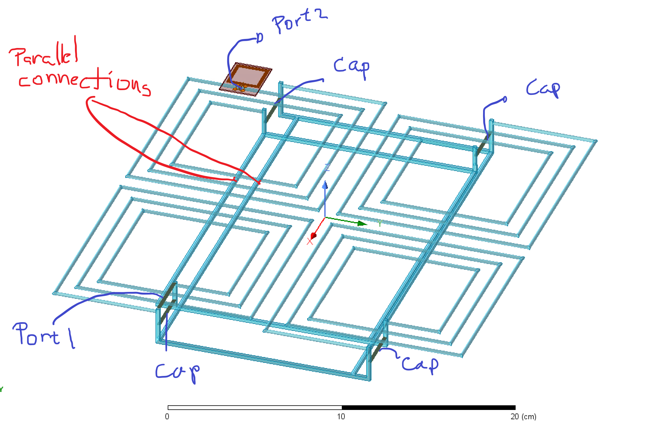
SubscriberI did this simulation: I put 4 coils in parallel as the transmitter and put a capacitor in parallel with each one of the coils , My question is: Is there any way to put the coils in parallel by placing a lumped port on each Transmitter coil with the same name to avoid drawing the parallel connections.

-
November 21, 2023 at 2:16 pm
Praneeth
Ansys EmployeeHi,
Kindly let us know whether you want to run a circuit or 3D simulation and your end goal. Please check my comments/suggestion as below:
- In the schematic the coils and capacitors are in parallel connection, but in the 3D model your coils are connected in parallel but arranged in an array fashion. Does your analysis require you to keep them in parallel?
- How are you ensuring that the Tx and Rx sides are coupled?
Kindly elaborate your design goals to help us serve you better.
Best regards,
Praneeth. -
November 21, 2023 at 2:44 pm
Miguel Gonzalez
SubscriberMy end goal is to obatain S21 from the input lumped port to the output lumped port.
- Yes , I need to keep the coils connected in parallel. I connected the coils in parallel using polylines , however I would like to know if there is a way to connect them in parallel by using a setting or something to avoid drawing this polylines.
- I ensure they are couple by calculating the mutual inductance by using the Z12 parameter between the input and output port
-
November 22, 2023 at 7:44 pm
Praneeth
Ansys EmployeePlease find my comments/suggestions in line with your responses
- I understand that you are keeping the coils side by side and connecting them in parallel. I recommend you check if they need to be on top of one another and connect them with fewer polylines for the parallel connection.
- Please let us know the frequency band in which you want to calculate the S-parameters.
Best regards,
Praneeth. -
November 22, 2023 at 8:23 pm
Miguel Gonzalez
Subscriber- No, they are not supposed to be on top but side by side to increase the covered area
- The system is supposed to operate at 13.56 MHz
-
December 6, 2023 at 2:46 pm
Praneeth
Ansys EmployeeHi,
Are you trying to do near field analysis or RFID simulation?
If yes, then you move the parallel connection to the bottom side of parallel coils so that they won't add any surprises to the simulation results.
Best regards,
Praneeth.
-
- The topic ‘Parallel resonace coil array’ is closed to new replies.


-
4974
-
1645
-
1386
-
1242
-
1021

© 2026 Copyright ANSYS, Inc. All rights reserved.


