您好,这两个问题的答案其实也藏在脚本代码里
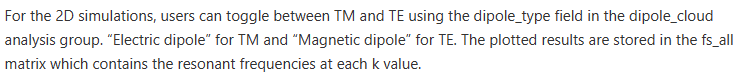
A1:案例里说dipole cloud中改变Electric dipole和Magnetic dipole可以获得TE或TM的能带图,细究代码,其实dipole_type用在了dipole光源的设置里,例如:
adddipole;
set(“theta”, rand*360);
set(“phi”,rand*360);
set(“dipole type”,dipole_type);
换言之,分析组里的这一项调整,实际的调整对象为偶极子光源的光源类型,在Lumerical官网的“Dipole source – Simulation object”一文里描述了这一项设置的含义,通过更换偶极子光源的类型,然后运行脚本计算,就能得到TE和TM的能带图。
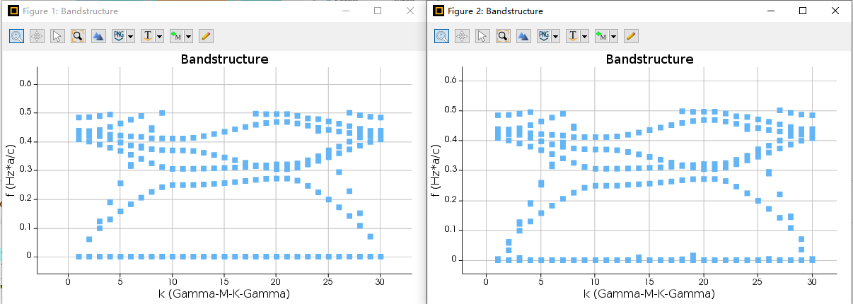
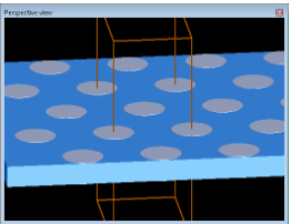
在“Bandstructure of planar photonic crystal with a hexagonal lattice”一文中,这个案例中上述的方法同样成立,我做了一下对应的仿真,发现图像其实是存在差异的,虽然差异较小,但确实是TE和TM两种不同的能带图。
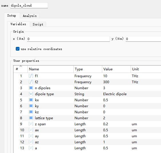
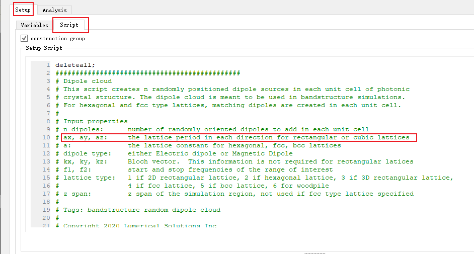
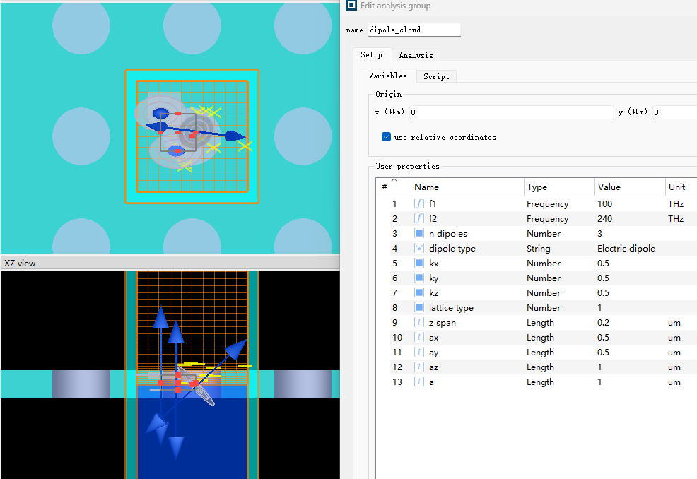
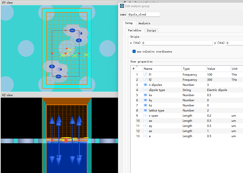
A2:案例的分析组脚本是六个案例通用的,相关参数也是,不同的案例由不同的lattice type决定,即:
# lattice type: 1 if 2D rectangular lattice, 2 if hexagonal lattice, 3 if 3D rectangular lattice,
#4 if fcc lattice, 5 if bcc lattice, 6 for woodpile
在平面结构里,az确实是没有意义的,例如latticetype==1时:
if (lattice_type==1){ # if rectangular 2D lattice
for(i=1:n_dipoles) {
adddipole;
set(“name”,”s”+num2str(i));
set(“override global source settings”,1);
set(“set frequency”,1);
set(“frequency start”,f1);
set(“frequency stop”,f2);
set(“x”,(rand-0.5)*ax*0.6);
set(“y”,(rand-0.5)*ay*0.6);
set(“z”,(rand-0.5)*z_span);
set(“phase”,rand*360);
set(“dipole type”,dipole_type);
set(“theta”,theta);
set(“phi”,rand*360);
}
}
并没有使用到az。
而对3D模型:
if (lattice_type==3) { # if 3D rectangular lattice
for(i=1:n_dipoles) {
adddipole;
set(“name”,”s”+num2str(i));
set(“override global source settings”,1);
set(“set frequency”,1);
set(“frequency start”,f1);
set(“frequency stop”,f2);
set(“x”,(rand-0.5)*ax*0.8); # keep dipoles 20% away from bloch boundaries to inject properly
set(“y”,(rand-0.5)*ay*0.8);
set(“z”,(rand-0.5)*az*0.8);
set(“phase”,rand*360);
set(“dipole type”,dipole_type);
set(“phi”,rand*360);
set(“theta”,rand*360);
}
}
az就起到了作用。
关于ax、ay、az如何定义周期,在您所说的模型里为何设置相同,也可以从代码看出。
如果对代码方面了解较少,可以参考“Lumerical scripting language – Alphabetical list”里的指令解释对应着来理解。