TAGGED: #Modal_Analysis, beam-element, geometry-import
-
-
November 3, 2023 at 9:25 pm
Jeffrey Lailey
SubscriberHello,
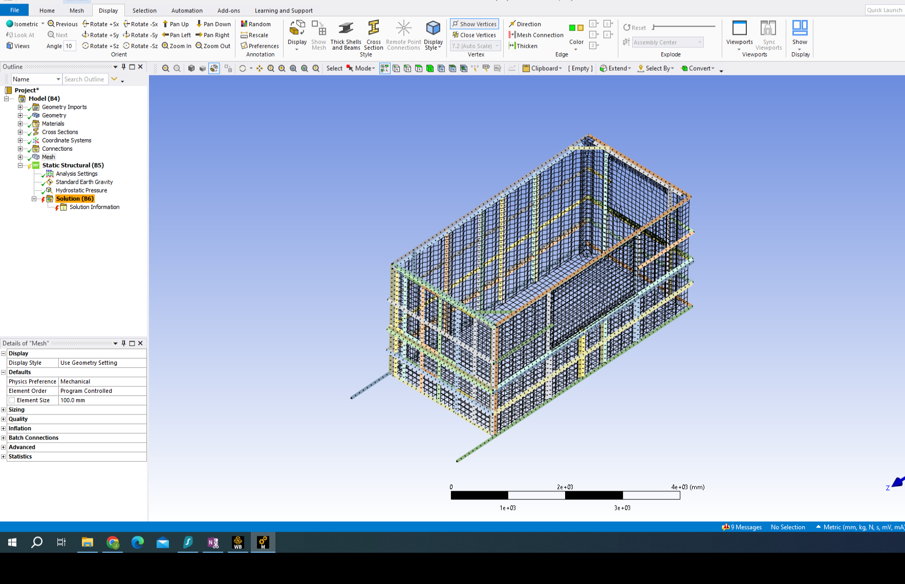
I am attempting to do a full model simulation from an old solidworks drawing I did of a shipping container pool. I was hoping to validate that I could do a larger full assembly simulation. I started by extracting all the beams so they show up as line bodies with the attached beam profiles. I took the window, wall and floor surfaces and midsurfaced them. I than did a batch connection all to all with a large connection size of 100mm and 50mm tolerance hoping that this would connect all of my beams and plates together. I was able to get a successful good looking mesh. I than ran a modal analysis to see what parts were not connected. I tried connecting the parts using bonded contact which seemed to make the model fail so I suppressed the parts that were free to see if I could get a simulation going but the more parts I suppressed different parts came up in the zero frequency modal analysis. I believe I have my hydrostatic pressure and standard earth gravity set up correctly. I also tried souppressing the corrugated sheet body of the shipping container to see if I could just get the beams to work for a simulation. I used a fixed to ground for the bottom of the shipping container. I am receiving a lot of error that I assume mean the container isn't constrained enough I am just wondering if there is a different way I should be going about this? Is there a way to visually check which connections have been made in batch connection? I was trying to attach beams to beams using mpc but the model seemed to fail after that. I also tried simplifying the model down to one wall and using auto generate connections. I tried manually selecting all the vertical beams and all the horizontal beams and adding a bonded connection as well with no success.
Error: A solver pivot warning or errors has been detected in the ROTY degree of freedom of node 8805
Error Solver pivot warnings or errors have been encountered during the solution.
One or more beams with a user- defined mesh cross sections have been sent to the solver as pre-integrated sections. Beam sections results will not be available.
Thanks for any input
-
November 7, 2023 at 5:34 am
Akshay Maniyar
Ansys EmployeeHi Jeffrey,
From what I gather, the approach you are taking appears to be correct. Have you used the contact tool to verify the open contacts? It will help you determine which contacts are causing issues. In order to ensure that the model does not produce any rigid body motion, you can also try running it with weak springs to see if that helps. After that, carefully review the results and add the missing contacts.
Have you also tried using share topology? It might avoid the use of contacts at many locations.
Thanks,
Akshay Maniyar
-
November 9, 2023 at 3:24 am
Jeffrey Lailey
SubscriberHi Akshay,
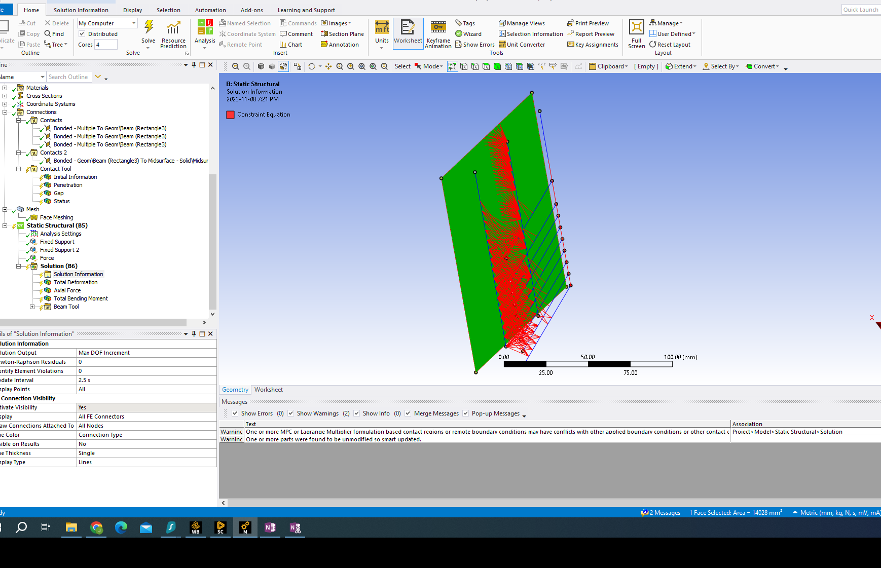
Thanks for taking the time to reply. I had tried using shared toplogy but as all the beams are structural tubing turned into line elements there is a gap between all of the beam elements and the surfaces. I had noticed doing a test project with multiple line elements and a midsurface body that trying to connect them all using MPC connections didn’t work. This seems to be caused by the nodes not being able to have MPC between a line body while simultaneously being connected to a surface body. Is there a way to connect multiple parallel line bodies and than connect those connected parallel line bodies to a midsurface? I had not tried the contact tool for my initial model but in using it for my test model it says some connections are inactive. Is there any way for me to use the weld feature in ansys to connect line bodies to midsurfaces? Is there anyway that I can connect specific nodes of the line bodies with the surface and than specific nodes with the line body?
Thanks
Jeff
-
November 19, 2023 at 11:05 pm
joseronaldo.15
SubscriberHi, you can send the proyect?
-
November 21, 2023 at 5:33 pm
Jeffrey Lailey
SubscriberHi Jose,
Thanks for the reply, what would be the best way to send it to you?
Thanks,
Jeff
-
-
November 20, 2023 at 8:02 am
Akshay Maniyar
Ansys EmployeeHi Jeff,
Can you use share topology only between all the line bodies and then use contacts or joints to connect the particular ends of line bodies to the surface body?
Thanks,
Akshay Maniyar
-
November 21, 2023 at 5:32 pm
Jeffrey Lailey
SubscriberHi Akshay,
Thank you for your reply. That is what I have started to try. In order to do this, from tutorials I have done, it looks like I need to move all the line bodies so they are touching and then offset them to their original position? The line bodies are supposed to be welded all the way along where they connect to the surface bodies, do you know if this will this be possible with connections? The other issue I ran into with making all the line bodies on the same plane is that I have two vertical line bodies that are parallel with each other so when I make them on the same plane they are in the exact same position. Any help is appreciated.
Thanks,
Jeff
-
-
- The topic ‘Connections and Process’ is closed to new replies.


-
4838
-
1587
-
1386
-
1242
-
1021

© 2026 Copyright ANSYS, Inc. All rights reserved.


