TAGGED: #mechanical-#workbench, simulation
-
-
November 2, 2023 at 2:14 pm
Muhammad Zeeshan
SubscriberHi there!
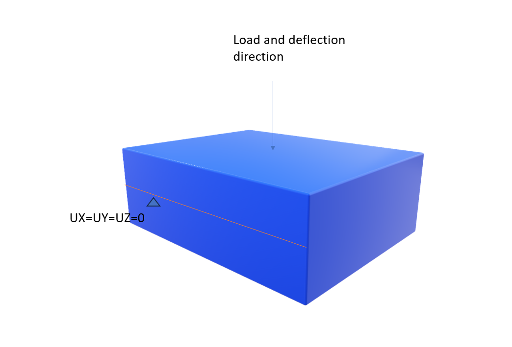
Looking for advice on what should be the closest and best possible depiction of a simply supported beam in Ansys?
I've an I-beam in terms of a solid body with its section built in XY plane while depth is extruded in Z plane.
Also, when putting in supports for an I-Beam, should i restrain the entire left/right edge (Bottom, top flange edge plus web) or just restraining the bottom left/right flange would be enough? Asking this because when we develop a line body, we just restrain one point. how about restraining for a body?
-
November 2, 2023 at 2:46 pm
-
November 2, 2023 at 2:48 pm
Muhammad Zeeshan
SubscriberHi Erik. Thanks a lot for your quick response. How about my first query on suitable boundary condition? I know I've to put remote displacement but i'm not sure what displacement & rotations should be restricted to depict exact simply sipported condition?
-
November 2, 2023 at 2:52 pm
Erik Kostson
Ansys EmployeeHi
You said:
”Looking for advice on what should be the closest and best possible depiction of a simply supported beam in Ansys?”
I have answered that – use what I am showing in the first post above (you do not need remote displacements).
Now if you want you can also use remote displacement on the end faces. See this post for details:
/forum/forums/topic/how-can-a-simply-supported-boundary-condition-be-defined-in-a-solid-model/
The method I showed is easier and does not use anything strange (say contact elements for remote point creation etc. which rem. disp. creates when used), it just applies the restrain on the nodes of that edge.
All the best
Erik
-
- The topic ‘Boundary Condition for Simply Supported’ is closed to new replies.


-
3572
-
1188
-
1076
-
1063
-
952

© 2025 Copyright ANSYS, Inc. All rights reserved.


