-
-
October 30, 2023 at 7:47 am
SujanAryal2
SubscriberHello,
I am simulating a 50 ohm microstrip line (lambda/2 at 1.5GHz) with source impedance (lumped port) of 50 ohms and load impedance (lumped port) of 50+1i*50 ohms. First I used the circuit analysis to obtain width and length of 50 ohms line. Since this is lambda/2 line, the input impedance should be equal to load impedance. I have attached the screenshot below which gave me good result ~50 ohms (to be specific it is 48.69+j*49..32) at 1.5GHZ.
However, when I used the same parameter to design it in HFSS model. I could not achieve the exact same values. The real part is off quite a lot. It is ~60 ohms. The screenshot are attached below. Since HFSS model doesnot support zin directly, I calculated Zin as output variables using Zin=Z11-(Z12*Z21)/(Z22+ZL) where ZL=Port2(Z) which is 50+j*50 when I checked it. Any help will be highly appreciated. For both case substrate is FR4_epoxy(4.4) and 1.67mm thick.
Â
Thank you.
-
November 6, 2023 at 1:40 pm
Sriparna De
Ansys EmployeeHi Sujan,
Thanks for asking the question in the forum.
Theoretical formula of effective permittivity is always some approximation of the actual fringing field behaviour. Whereas HFSS solves Maxwell equation in 3D space and estimates the actual field interaction. So, what you are calculating for the length of transmission line as lambda/2 according to the formula of effective permittivity is not the same in actual scenario. So you have to tune the length accordingly to get the exact matching.
Moreover, in HFSS, port impedance will be 50ohm only. In the equation of Z_in, you have to mention about the load impedance value e.g. Â ZL=50+j50 as you mentioned above.
-
- The topic ‘
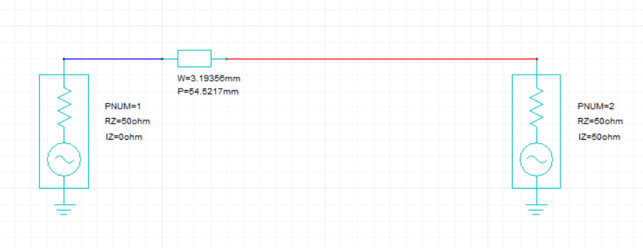
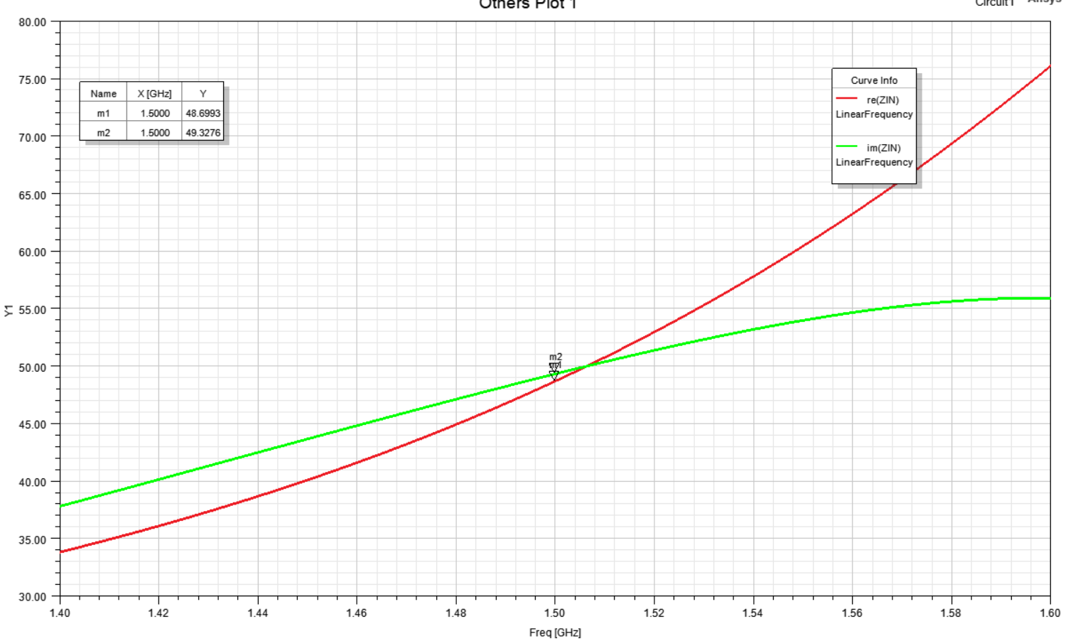
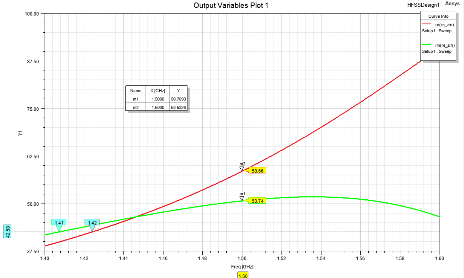
Microstrip line is not working as expected in HFSS’ is closed to new replies.
-
4703
-
1565
-
1386
-
1242
-
1021
© 2025 Copyright ANSYS, Inc. All rights reserved.


