TAGGED: cfd-post
-
-
October 28, 2023 at 9:46 pm
ksoltyk
SubscriberHello Ansys community,
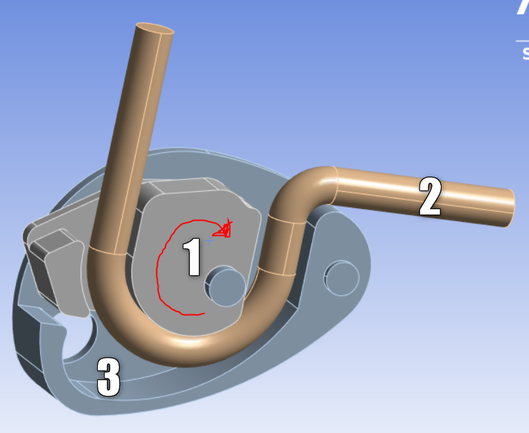
I am currently working on an analysis of a mechanical device (Solid 1 and Solid 3) where the primary goal is to accurately represent the physics of the device, and not to analyze the rope itself. For this purpose, I've created the rope (referred to as Body 2) as a single solid. I apply either displacement or force to one end of the rope, and due to the friction between the rope and the curved part of solid 1, it causes solid 1 to rotate and squeeze the rope between solid 1 and solid 3.
The rope is composed of multiple individual fibers and has low transverse stiffness; it is not a homogeneous block of isotropic material, and the individual fibers are not bonded together. My question is: what is the simplest and most effective way to represent the properties of this rope in Ansys?
Is the main challenge here to define the rope as an orthotropic material? I'm quite new to using Ansys, and I'm struggling to find the right approach to model such a rope accurately.
Any help or guidance on how to model this rope in Ansys would be greatly appreciated. Thank you in advance for your assistance. I'm an amateur in using the Ansys software, and I'm having difficulty finding the solution to this particular modeling problem.
-
October 30, 2023 at 1:58 pm
dlooman
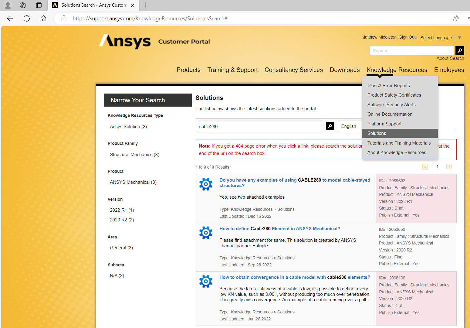
Ansys EmployeeIt would be more practical to model the rope with the cable280 element. Use a small contact stiffness factor between the cable280 and the surfaces of the solid bodies to help convergence. With a 3D model of the rope it will be difficult to simulate the low bending stiffness, but more importantly, will be hard to solve for a large amount of motion.
-
October 30, 2023 at 9:20 pm
mjmiddle
Ansys EmployeeAre you using workbench Mechanical or APDL GUI?
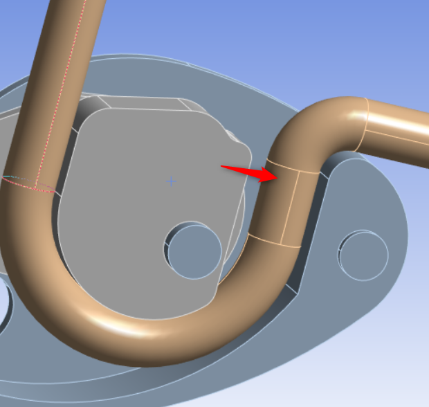
Use SpaceClaim or DesignModeler to define a beam with cross section. You may need to share topology on line and arc segments.
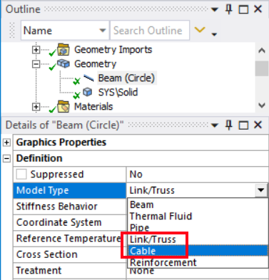
In Mechanical, in the Details of the beam under Geometry, set the "Model Type" to either "Link/Truss" or "Cable."
The Link/truss will make link180, which is a linear element (2 end nodes). The cable will make cable280, which is the quadratic version of the element (2 endnodes, and a mid node), if the Mesh setting is not set to linear.
https://ansyshelp.ansys.com/account/secured?returnurl=/Views/Secured/corp/v232/en/wb_sim/ds_line_bodies.html?q=cable
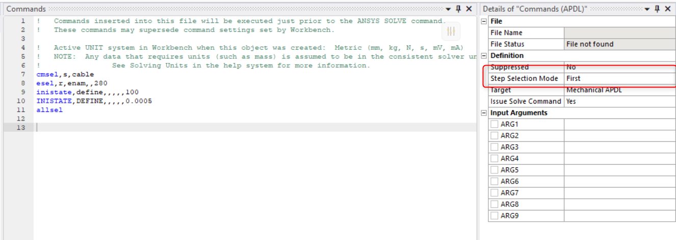
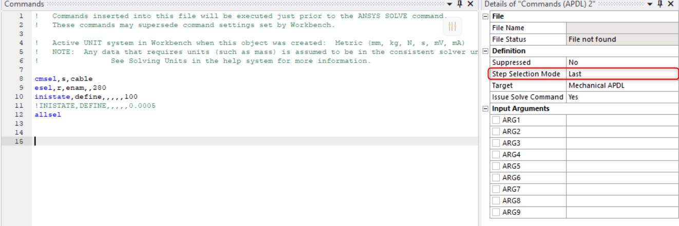
1. Command object is necessary (inistate) in the environment setup (Static Structural) to put some initial stress (tension) on the link180 or cable280. This is necessary in static simulations since the cable is just a bunch of pinned link elements now. Imagine holding up a chain in space (no gravity) the links have no lateral stiffness w/o tension.
cmsel,s,cable ! place the geometry edges in a named selection first, name "cable" in this case
esel,r,enam,,180 ! Or use 280. may be necessary if there are contacts scoped to the line bodies, since overlain contact elements are created on the line bodies
inistate,define,,,,,100 ! to define an initial stress
!inistate,set,dtyp,epel ! or set an initial strain
!INISTATE,DEFINE,,,,,0.0005
allsel2. Large deflections must be on
3. At least 2 load steps. In first load step, a constraint mush keep the cable from contracting due to inital stress (inistate). Deactivate this constraint in the second load step and apply other loads in second load step.
4. link180 has to be meshed very fine to prevent a faceting behavior as it still is just a bunch of links. Cable280 can use less elements.
5. Substep size should be limited to be small enough so that the contact between the link180/cable280 and the surface does not change status too quickly, otherwise you may see the cable penetrate the solid if displacements change too quickly, pinball (next bullet point) should be set sufficiently large to help prevent this as well.
6. Pinball region on contact should be made bigger than default. Make sure it is larger than the gap between the cable center represented by the beam and the 3D body faces. Specify the "Offset" for the "Interface treatment" or "Adjust to touch." If this is hard to converge and the cable is small diameter you can model the center of the cable (beam representation) to lay the 3D bodies in the CAD modeler, which will be easier to converge. -
October 30, 2023 at 9:27 pm
-
November 29, 2023 at 11:28 pm
ksoltyk
Subscriber -
November 29, 2023 at 11:30 pm
ksoltyk
Subscriber- I have enabled large deformations.
- I divided the line into smaller segments (there will be many more of them later; for now, there are just a few to try) and set the type to "cable" to create CABLE280 elements. Each element represents a separate volume.
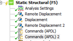
- I added two APDL scripts to apply initial stresses to the line, one in the first load step and the other in the second load step.
- I set the "Pinball Region" at the contact area between the cable and the surface.
- My questions are: where are my mistakes? Is modeling the cable using CABLE280 elements supposed to involve separate geometries? Are adding scripts to apply initial stresses in the first load step and deactivate them in the second load step done correctly? Should scripts be added in "Analysis Settings"? Does anyone have any videos or websites that solve problems involving cables using CABLE280 or LINK180 elements? I would be very grateful for any help; I don't kno
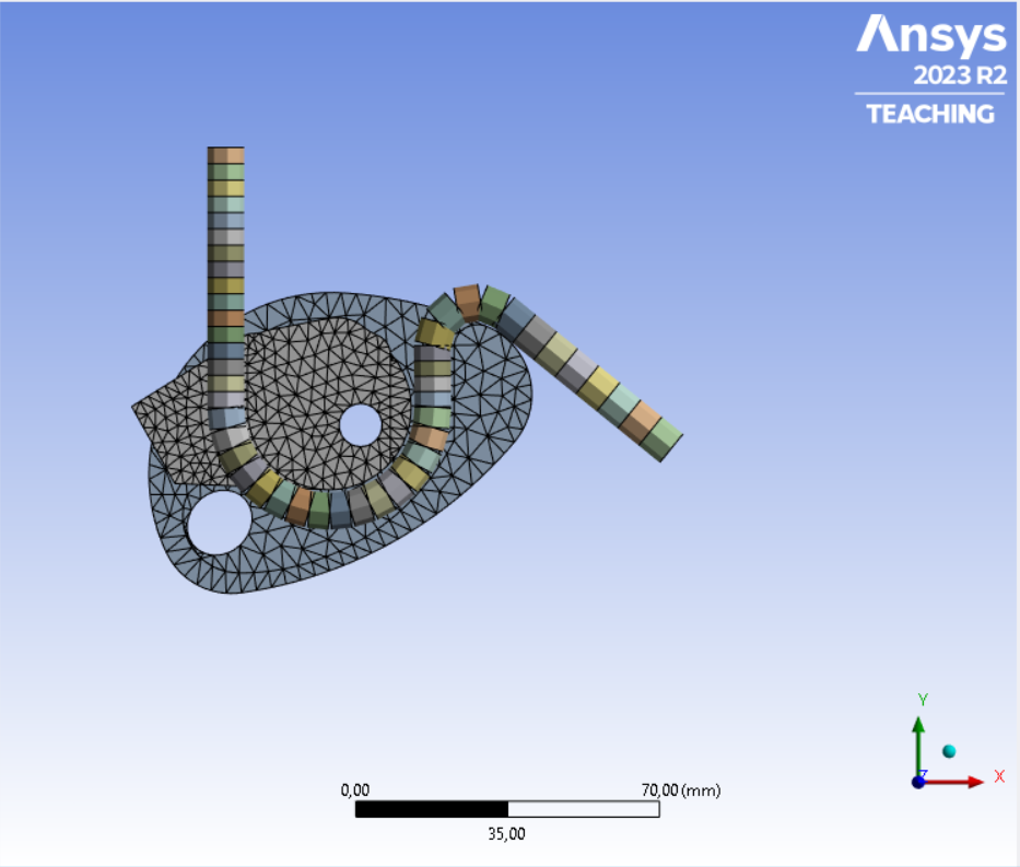
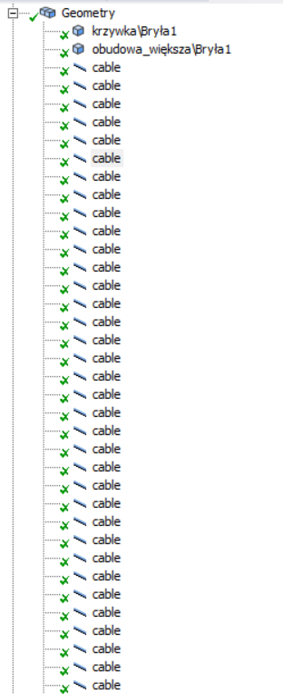 w what to do.
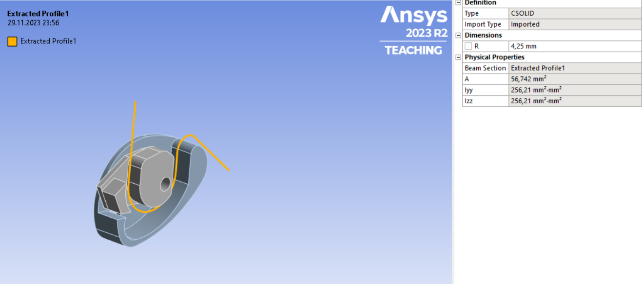
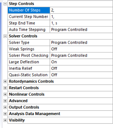

-
- The topic ‘How to Model a Rope in Ansys for a Mechanical Analysis’ is closed to new replies.


-
4833
-
1587
-
1386
-
1242
-
1021

© 2026 Copyright ANSYS, Inc. All rights reserved.

