Hi,
I am working on a 2D rotor blade profile. I have created three cell zones.Starting from the left direction I named them part 1,part 2 and part 3.The rotational speed is 74.6 rad/sec (712 rpm)for part 2 while the remaining two of them are stationary.It's a transient simulation with fractional step method.

Inside the cell zone condition, i have selected the frame motion for part 2(rotor cell zone) as shown below:

And additionally, I have opted for moving wall as shown below which is at a zero relative velocity with reference to the adjacent cell zone as shown below
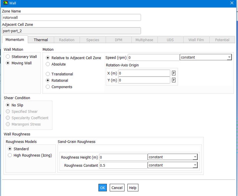
When I am post processing the result for the resultant streamlines,I cannot see swirl on the exit of the rotor.Also,the moving wall as selected doesn't seems to move with time.What i am getting instead are straight streamlines as shown below:

Could you please tell me how do i resolve this issue of non-moving wall and no exit swirl.Additionally, I am also getting reverse flow conditions at the pressure inlet and outlet faces.
Thank you


