-
-
October 22, 2023 at 7:29 am
Tianyuan Wang
SubscriberDeal all
For a coaxial double-buoy device, e.g., RM3, the two bodies are only allowed to move relative to each other in the heave direction. In the linear frequency-domain calculations, the wave-excitation loads are obtained by fixing the two objects without any motion. On the other hand, the wave-radiation loads are obtained by forcing one of the objects to move with unit ampitude in one direction.
For example, added mass coefficient matrix of the two objects has a size of 12*12. Added mass A(3,3) is obtained by forcing object 1 to move with unit ampitude in the heave direction, and A(3,9) is the added mass imposed on object 2 by the forced motion of object 1 in the heave direction. However, due to the rigid constraint between the two bodies, I don’t think the added mass and radiation damping can be implemented in the surge direction.
Specifically, the added mass A(1,1) is obtained by forcing object 1 to move with unit ampitude in the surge direction, and A(1,7) is the added mass imposed on object 2 by the forced motion of object 1 in the surge direction. Likewise, A(7,7) is obtained by forcing object 2 to move in the surge direction, and A(7,1) is the added mass imposed on object 1 by the forced motion of object 2 in the surge direction.
Considering the existence of rigid constraints between the two bodies, should the radiation coefficients be calculated in the surge, sway, roll, pitch and yaw directions? For the outer bodies with a moonpool, the forced motions of one of the two objects in the five directions would cause large-amplitude radiation waves, especially if the gap between the two objects is small.
For the RM3 device with a structural height of 38 m, radiation waves generated by the forced motion of inner body in the pitch direction are monitored to be as high as a few hundred meters, and the radiation waves generated by that in the surge direction are tens of meters. This is obviously not normal. I think it has something to do with the forced motion of a single object. Can AQWA implement constraints between two objects in frequency-domain calculations, and could you please give me some suggestions on this issue?
Best regards, Tianyuan
-
October 23, 2023 at 5:50 pm
Mike Pettit
Ansys EmployeeHi Tianyuan,
Sorry it took me a while to reply to your post in the other thread. I will copy my response here as well.
You can create constraints between structures in the Hydrodynamic Diffraction analysis by using one or more linear Connection Stiffness matrices. These can be defined between the ground and a structure, or between two structures. For example, if you create a Connection Stiffness matrix between the float and the central column, then define large values for X-X, Y-Y, RX-RX, RY-RY, RZ-RZ and leave all other terms as zero, the float will be constrained so that its relative motion with respect to the column is almost completely in the Z direction.
Connection Stiffness only affects the Hydrodynamic Diffraction analysis. It is assumed that the effect of the Connection Stiffness is replaced by actual modelled connections (e.g. an arrangement of fenders) in any downstream Hydrodynamic Response calculations.
I hope this helps!
Mike
-
October 24, 2023 at 6:33 am
Tianyuan Wang
SubscriberHi Mike
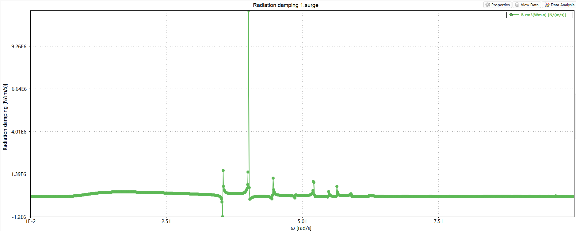
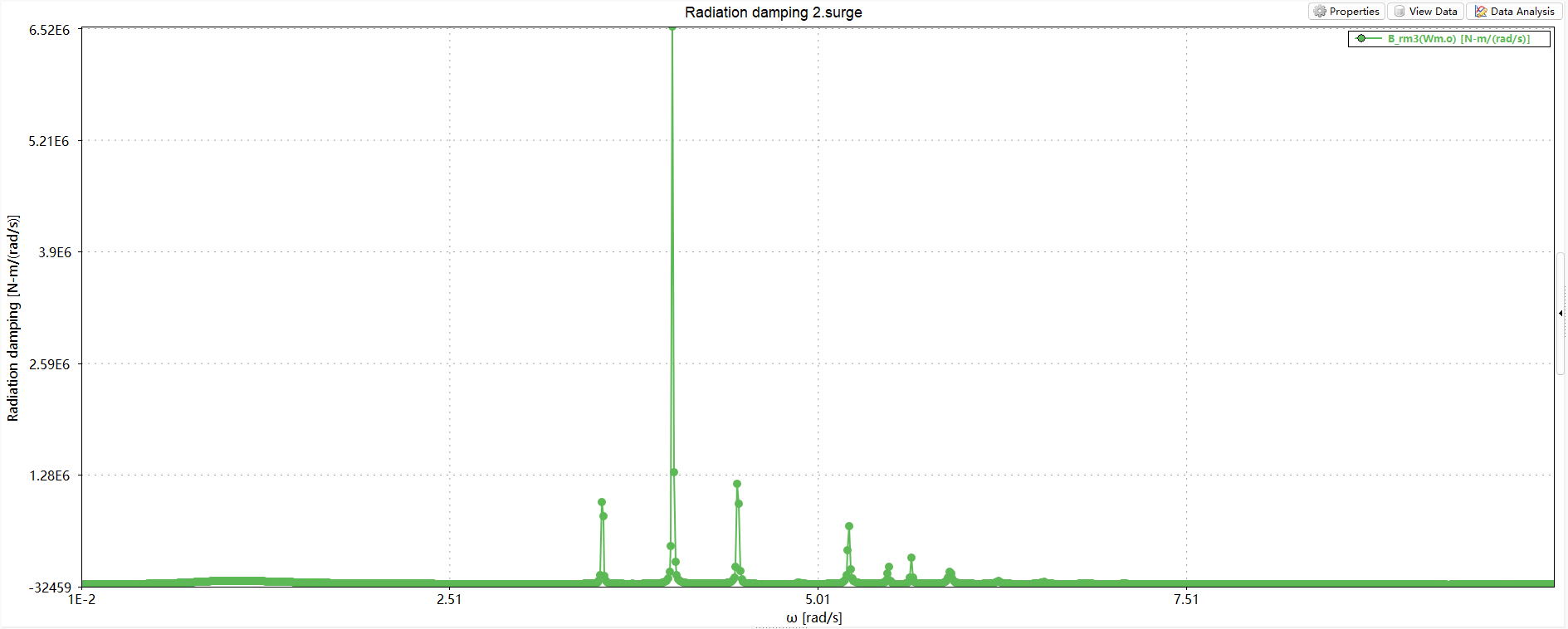
Thanks for your reply. I’m worried about the calculation of the radiation loads. Although the constraints are established between two objects, the added mass and radiation damping coefficients are still obtained by exerting objects’ forced motion. The forced motion would cause narrow gap resonance phenomena. For exmaple, in the surge direction, the outer object is fixed and the inner object moves in a harmonic motion with unit amplitude. This will overestimate the radiation waves in the gap and cause strange peaks around resonant frequency in added mass and radiation damping. But in physics, such singular peaks do not exist due to constraints between two objects.
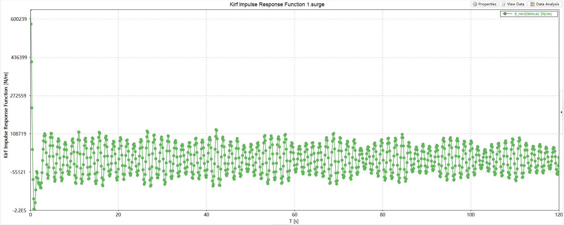
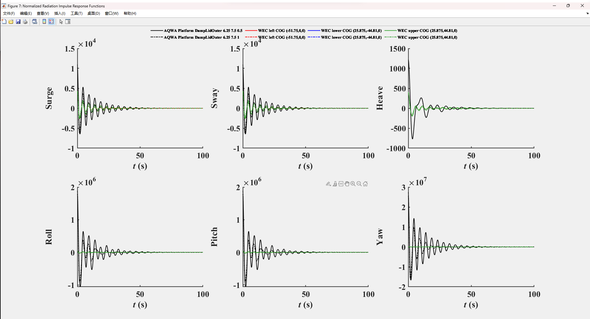
The incorrect radiation damping coefficients gererate the incorrect radiation impulse response function when convolution integral is activated. I’m worried that this will affect the time domain calculations. How AQWA solved the problem?
Best regards,
Tianyuan
-
October 25, 2023 at 11:47 am
Mike Pettit
Ansys EmployeeHi Tianyuan,
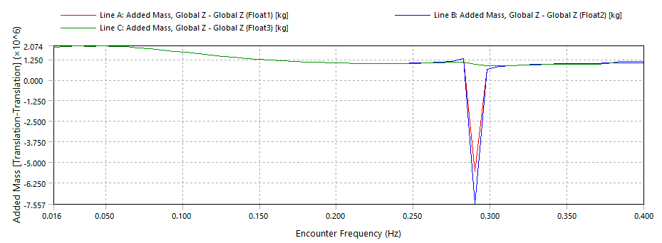
This is where the External Lid becomes important. I have set up an example where there is a 0.4 m gap between the float and the column, and I have used a Connection Stiffness matrix to constrain the float with respect to the column. For comparison I have created the float/column pair both with and without an External Lid in the 0.4 m gap. The lid is set with a damping factor of 1.0. In the following graph of heave added mass, the red line is the float without the lid; the green line is the float with the lid (don't worry about the blue line!)
-
November 4, 2023 at 6:44 am
Tianyuan Wang
SubscriberHello Mike
I guess you don't get post notifications. Do you have any suggestions for the problem?
Best regards,
Tianyuan
-
November 8, 2023 at 3:57 pm
Mike Pettit
Ansys EmployeeHi Tianyuan,
You are correct that the Connection Stiffness will only affect the calculated RAOs, i.e. the added mass and radiation damping are not modified.
However, if you have defined Connection Stiffness in the diffraction analysis, I would expect that your Hydrodynamic Response model also includes some kind of constraint, for example an arrangement of fenders to prevent motion of the float in surge/sway/rotation relative to the column. Therefore only the heave impulse response function is significant in the time domain.
Alternatively, if you are using Release 2022 R1 or later, you can set the Hydrodynamic Response analysis to include the Connection Stiffness matrix. You will need to turn on Beta Options in Workbench, then you should see the option 'Include Linear Connection Stiffness Matrices' in the Hydrodynamic Response Analysis Settings.
Cheers, Mike
-
November 9, 2023 at 7:36 am
Tianyuan Wang
SubscriberHi Mike
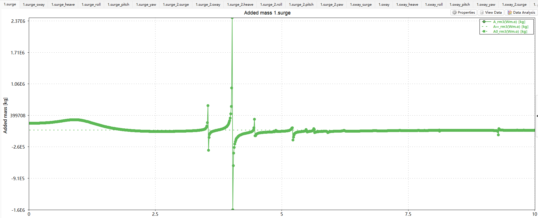
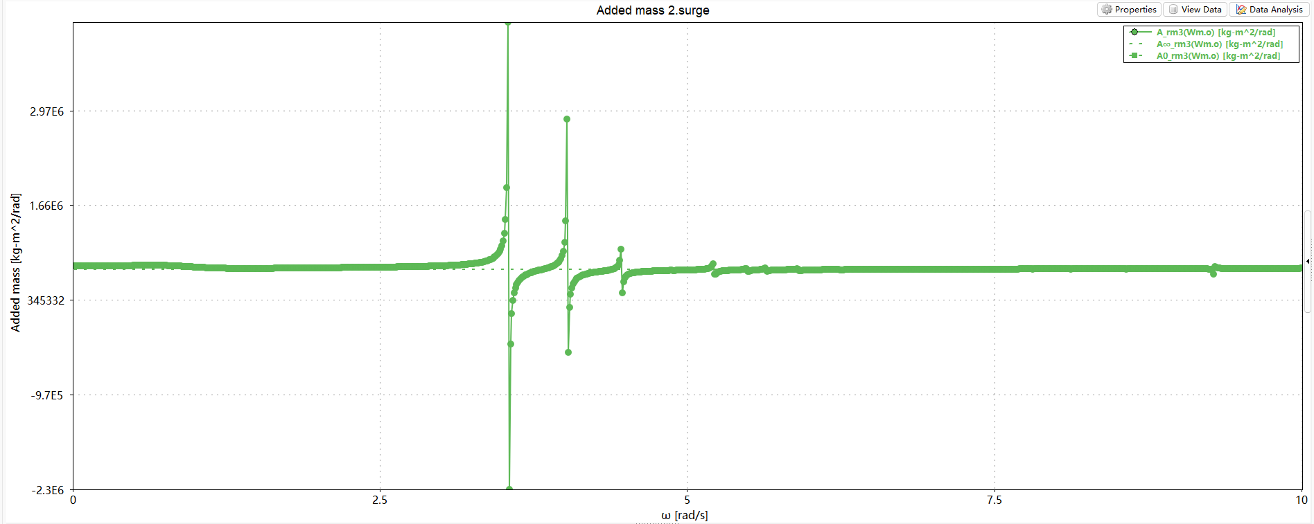
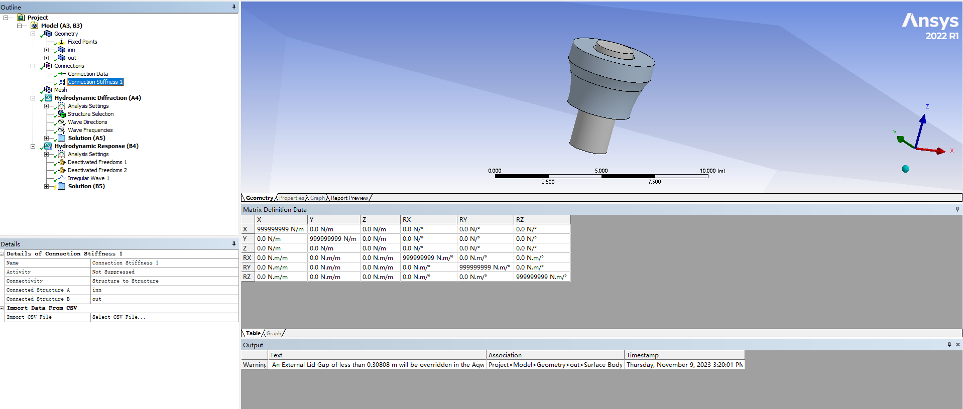
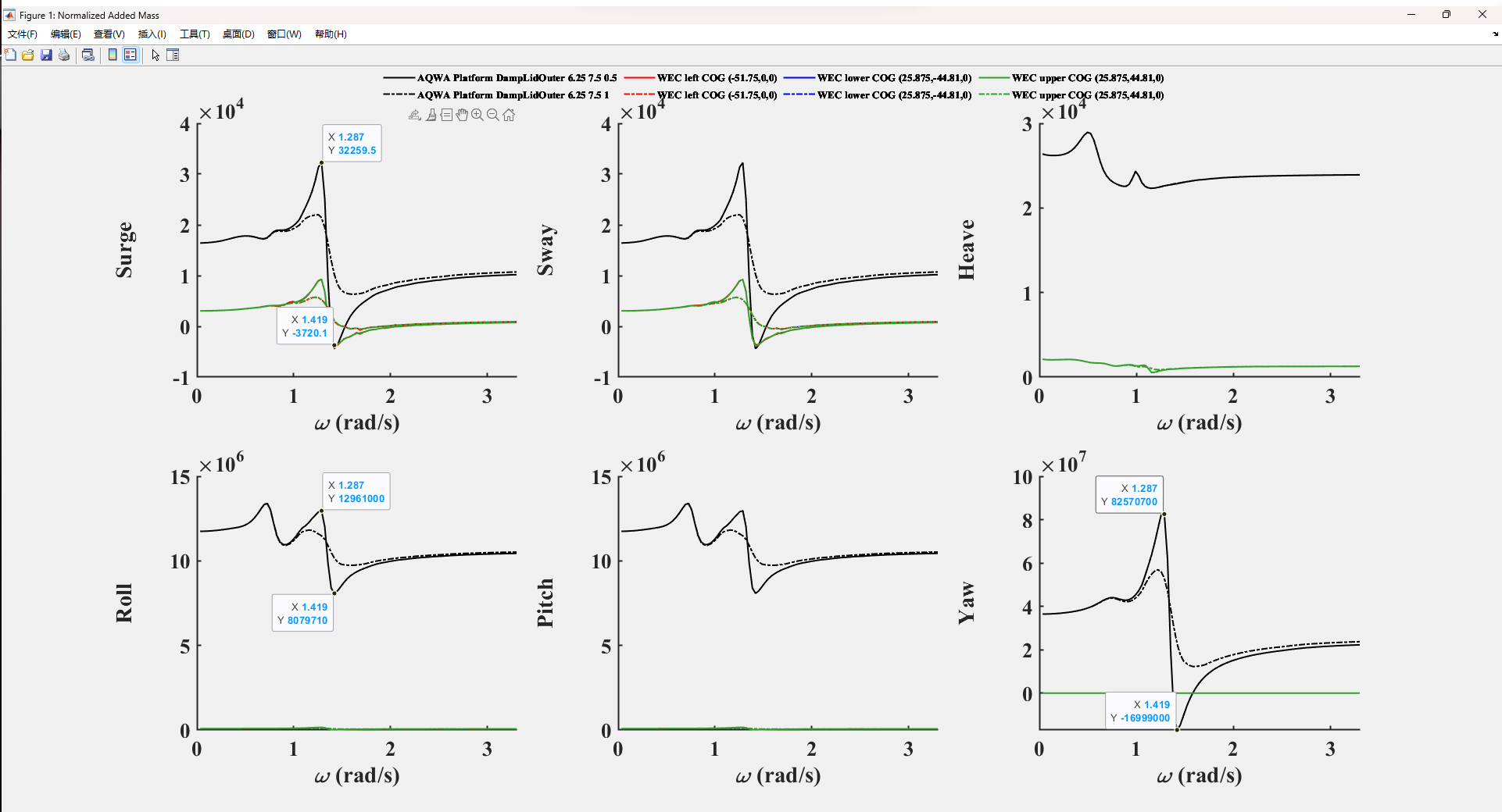
I add a Connection Stiffness matrix between two objects, but the hydrodynamic coefficients are not changed and strange peaks still exist in the surge, sway, roll and pitch directions. Is there a problem with my operation?
This issue has indeed been bothering me for a long time. Unfortunately, I haven’t found a good solution for it yet. Is there any other solution on it?
Added mass of inner body in the surge direction, no External Lid
Added mass of inner body in the surge direction, Damping Factor of the External Lid is 1, no Connection Stiffness matrix
Added mass of inner body in the surge direction, Damping Factor of the External Lid is 1, Connection Stiffness matrix is diag([9999999,9999999,0,9999999,9999999,9999999])
Best regards,
Tianyuan
-
November 17, 2023 at 3:05 pm
Mike Pettit
Ansys EmployeeHi Tianyuan,
You should not expect the Connection Stiffness to change the added mass or radiation damping calculated by Aqwa. As you say, these are related to the forced vessel motion, but we do not care how much 'force' is required for that motion.
I don't think you need to worry about the spikes in the added mass/damping plots, as long as the heave terms are sensible. If you have constrained the structures in the time domain calculation, there will be no relative motion in surge/sway/roll/pitch, so there will be no radiation force in these directions.
I'm sorry that I didn't explain the Connection Stiffness definition well. To model the sliding connection between two structures in the Hydrodynamic Diffraction calculation, you should:
- add three Connection Stiffness objects under Connections
- for each Connection Stiffness, set the 'Connectivity' to 'Structure to Structure'
- set the 'Connected Structure A/B' as
Connected Structure AConnected Structure BConnection Stiffness 1Component1Component1Connection Stiffness 2Component2Component2Connection Stiffness 3Component1Component2- for Connection Stiffness 1 and 2, set the stiffness values as e.g. K11 = K22 = 1e10 N/m; K44 = K55 = K66 = 1e12 N.m/deg (leave K33 as zero to allow relative heave motion)
- for Connection Stiffness 3, set the stiffness values as e.g. K11 = K22 = -1e10 N/m; K44 = K55 = K66 = -1e12 N.m/deg (leave K33 as zero to allow relative heave motion)
Rather than using the arbitrary large stiffness values of 1e10 N/m and 1e12 N.m/deg, you may consider selecting values based on the structural mass/inertia terms, so that the natural frequency of the system is higher than the wave frequencies you are including in your hydrodynamic analysis.Mike
-
-
-
October 25, 2023 at 1:21 pm
Tianyuan Wang
SubscriberHi Mike
Here are my opinions. Please correct me if something is wrong:
- In the frequency domain calculation, constraints affect only the RAO of the floating bodies but have no effect on the radiation coefficients, because radiation coefficients are obtained by forced motions (ignoring any constraints).
- As for my studied floating platform, the gap between the platform and ring-shaped float is 1.25m, and an External Lid is attached on the outer torus, with a width of 0.75m and different Lid Damping Factors. Although the Lid Damping Factor is increased to 1, the strange peaks still appear around omega ~ 1.25-1.4 rad/s. I found the strange peak omega ~ 0.28 Hz is eliminated using Lid Damping Factor = 1, but it does not seem to work for my model. Therefore, I am worrying whether the strange peaks in the surge, sway, roll, pitch and yaw directions are caused by the narrow gap resonance? Or generated by the forced motions? If the strange peaks (in the surge, sway, roll, pitch and yaw directions) are caused by the relative motion of two floating bodies during the forced motions (they don’t actually exist because of the constraints), what should be done with it? In fact, I’m concerned about the radiation IRF results. The External Lid has little effect on the radiation coefficients in the heave direction but has a significant effect on the other five directions. So I hypothesized that the strange peaks might be due to forced motions but not the narrow gap resonance. Improper handling of radiation damping will directly affect the radiation IRF and ultimately the time-domain results. Could you please give me some suggestions on it. Many thanks !
Best regards,
Tianyuan
-
- The topic ‘Implement of constraints between two objects in frequency-domain calculations’ is closed to new replies.


-
4527
-
1494
-
1386
-
1209
-
1021

© 2025 Copyright ANSYS, Inc. All rights reserved.


