TAGGED: bonded-contact
-
-
October 12, 2023 at 8:23 pm
bezi.khoubeib
SubscriberI am running a simulation of a Tensile Test of a composite Material Modeled as 20 Layers assigned different material properties.
(Tensile force on the x-axis. 20 solid bodies of different materials stacked on the z-axis.)
I have a two types of bonded contacts to consider:
1- The contact areas are on the common surfaces between each two Layers are selected. (Upper Layer: Lower surface. Lower Layer:Upper surface)
2- For each one of the two successive Material Layers involved in the contact pair: The upper AND the Lower surfaces of each layer is selected as contact surfaces.
Â
- The problem is that when using the second type of contact definition (automatically generated, but removed the pairs with no contact), the results I come across are more consistent with the experimental value obtained of the linear elastic module during the tensile test I am trying to simulate.Â
- Does using the second set of contacts make sens? The initial contact tool (before solving) shows no open pairs. (no red, yellow, orange. only white and gray pairs)
Thank you for your help.
Regards,
Vanderbezi
-
October 16, 2023 at 6:20 pm
mjmiddle
Ansys Employee
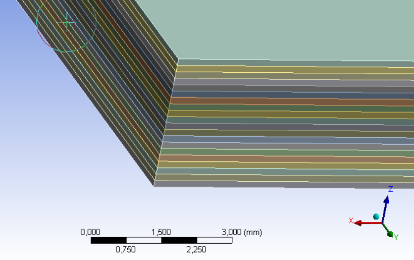
I am a bit confused at your description, but I think by your method 2, you mean it is automatically making contact pairs where both sides (top and bottom faces) of one particular solid body layer are selected for one side of the contact ("contact" or "target" side). While contacts can sometimes be set up with multiple, disconnected geometry selections for each geometry side, this can be problematic. For one example, only one location has to report as touching in contact detection for the solver to think it's touching, when some locations may not be in contact at all. On this case, I think it is very wrong, because it may form a solid connection across the layer, which would ignore the layer's stiffness contribution.
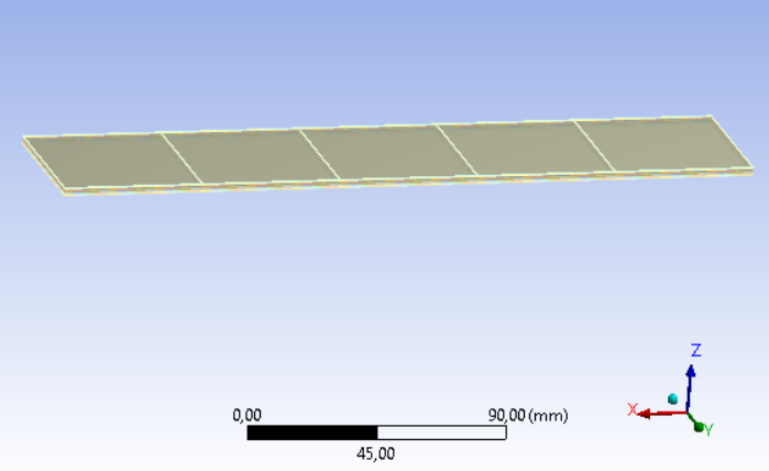
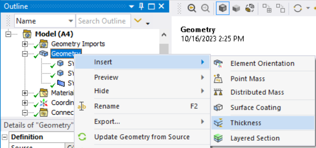
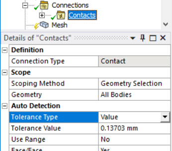
This setup happens when the tolerance for contact detection is too high. This is typical when there are small features within a model that has an overall larger bounding box. This layers are thin compared to the overall model size. You should set the "Tolerance Type" to "Value" on the Contacts folder under Connections group in the Outline, and enter a size less than the layer thickness.
Delete your current contacts first, then right click on the Contacts folder or Connections group to "Create Automatic Connections."
Note that you can also manually create each contact if you don't like what was automatically created.Â
-
October 16, 2023 at 6:28 pm
mjmiddle
Ansys EmployeeYou should also consider some other methods of modeling this stackup.
1. You could share topology in SpaceClaim or DesignModeler so that it meshes all these layers as node-connected. No contacts will be needed and material is perfectly bonded.Â
2. You could use Ansys Composite PrepPost (ACP) to define the stackup, especially if material has orthogonal properties.
3. You could also just use one surface geometry at the top or bottom, and right click on Geometry to "Insert > Thicknes"
Turn on worksheet mode, and you can right click in the spreadsheet to add each layer. Specify the material, thickness and optionally, an angle orientation for each layer. This is a very efficient way to model the stackup.
-
- The topic ‘Bonded contacts within a modeled composite Material’ is closed to new replies.
-
3572
-
1188
-
1076
-
1063
-
952
© 2025 Copyright ANSYS, Inc. All rights reserved.