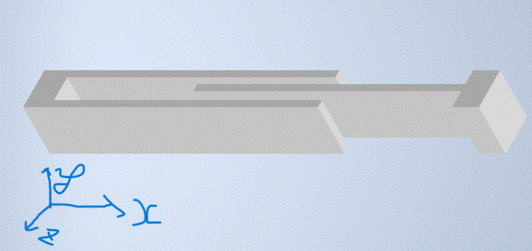
You of course need to create an "air box" geometry - a domain that includes the gaps between the fingers and an amount of the space extending beyond the them, sort of like what's shown in the image below (a few of the "air box" external face were hidden to expose the finger geometry inside):
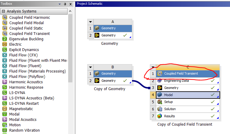
Perform a Boolean operation - subtract the fingers of the comb drive from the air box. You can keep the finger geometry, though depending on your objective you may not need to include it in the analysis (if not, simply suppress the geometry). I would recommend forming a single part comprising all the geometry (no contact will be created in Mechanical). I would recommend using a Coupled FIeld analysis system:
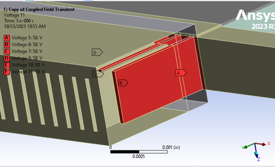
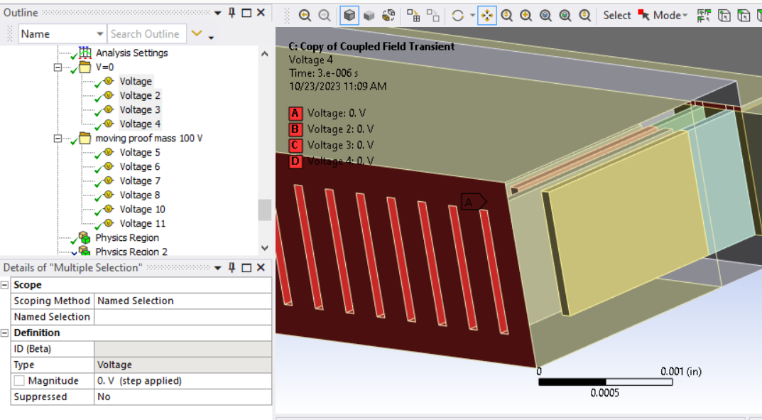
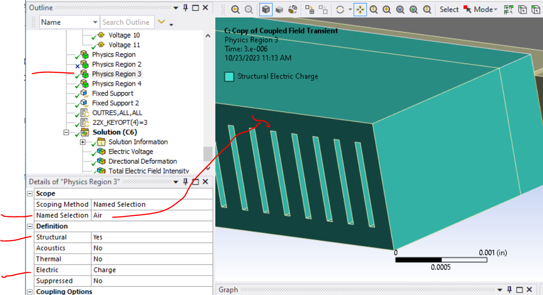
Apply one value of voltage to one set of (moveable) fingers as shown in red in my first image and another value of voltage to the other (stationary) set of fingers as show below.
I beleive the Coupled Field analysis system will require you to include structural as well as charge based electrostatic DOFs in at least on part of the model:
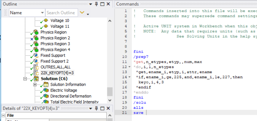
If you want to accomodate motion/mesh deformation in the "air" that results from motion of the fingers (which can be problematic) try using a linear tet mesh and a command object to set this keyoption in the air mesh:
In the sceanario I'm considering, the air will have structural DOFs and so needs to have a finite elestic modulus, which you want to make negligibly small but large enough so as to not produce ill-conditioned system matrix. Try ~ 20 Pa, and make Poisson's ratio = 0.
Parametrization is done in the upstream CAD application (e.g., Space Claim or Design Modeler) used to create the geometry. You might have better luck bringing geometry with micron scale features into Mechanical if you use Design Modeler.
In post processing you can insert charge reaction probes. With the charge reaction and applied voltage you can deduce capacitance.
--Bill