-
-
October 4, 2023 at 1:49 pm
Gabriel Coêlho
SubscriberHello everyone,
This is my first post in this forum, so sorry if I am using it wrong.
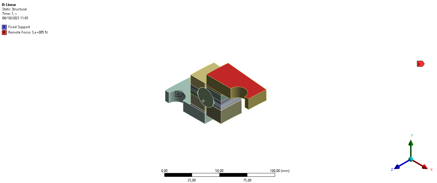
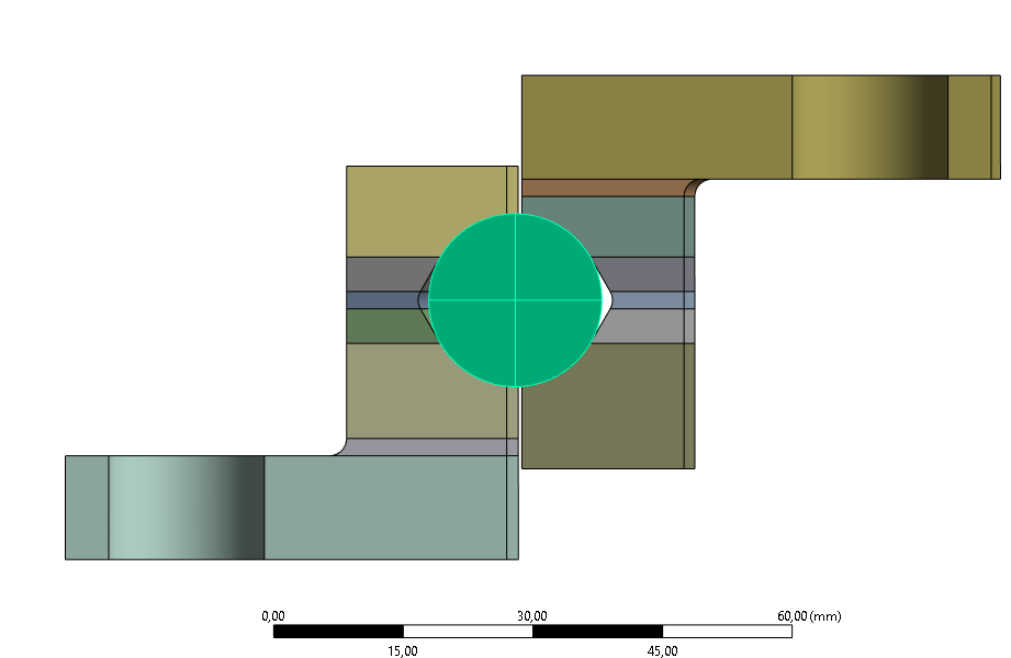
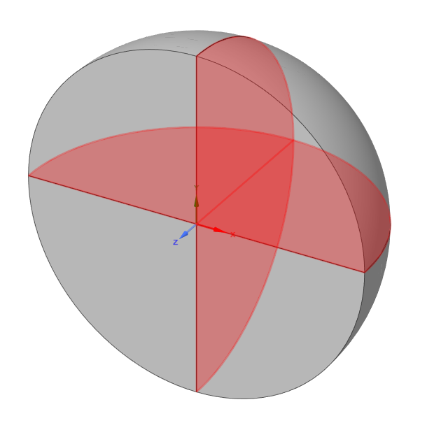
I am trying to model a portion of a bearing (static), as shown below. I am trying to model the sphere as a rigid body and the rest as flexible. When i try to solve, I get the following error: All bodies under this part must have the same setting for stiffness behavior. Please modify this setting on each body. I don't understand why. On Spaceclaim, the parts are defined as different components. Any thoughts?
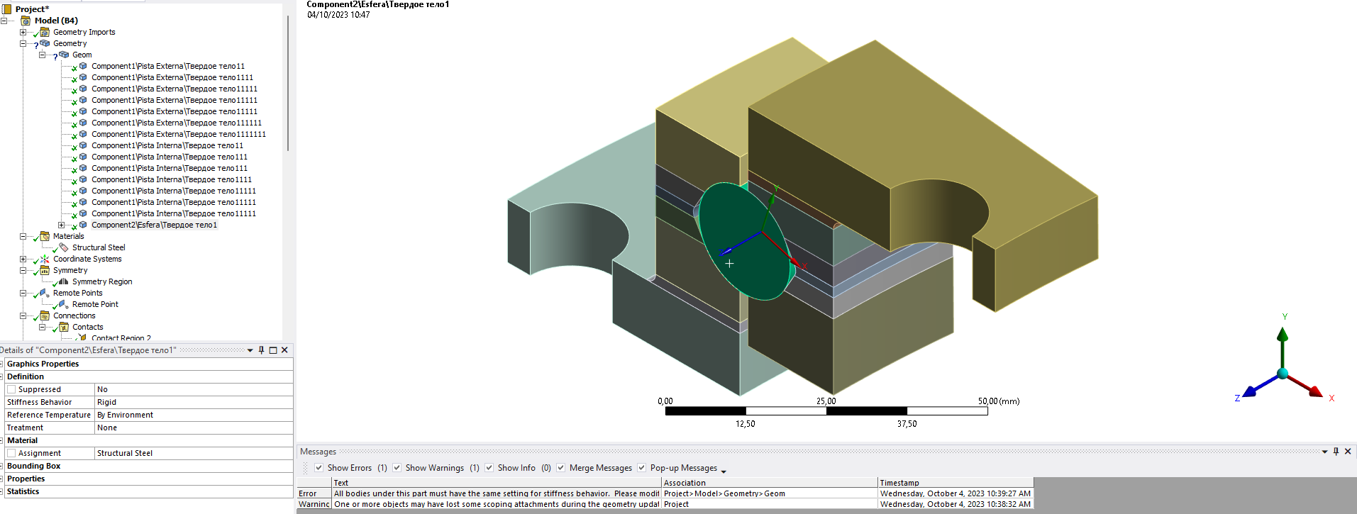
-
October 4, 2023 at 2:39 pm
Sampat Kumar
Ansys EmployeeHi Gabriel,
What are the boundary conditions that you have applied? Please let me know.
Regards,
Sampat-
October 4, 2023 at 2:47 pm
-
-
October 5, 2023 at 8:01 am
Sampat Kumar
Ansys EmployeeHi Gabriel,
Please unshare the shared topology under the workbench tab in SpaceClaim and perform the shared operation only on those parts that are to be shared by using the share option under the workbench tab in SpaceClaim. You can hide the other parts of the geometry that are not to be shared while using the shared topology on the specific part. Make a separate component of the rigid and flexible parts under the geometry in the SpaceClaim. It looks like all the geometry components are under "Geom" in your case. Both components should be under "geometry."
Regards,
Sampat-
October 5, 2023 at 1:01 pm
Gabriel Coêlho
SubscriberHi Sampat,
I've done what you suggested, and it seems to work, I can now define the sphere as rigid with no "?" on geometry on the tree.
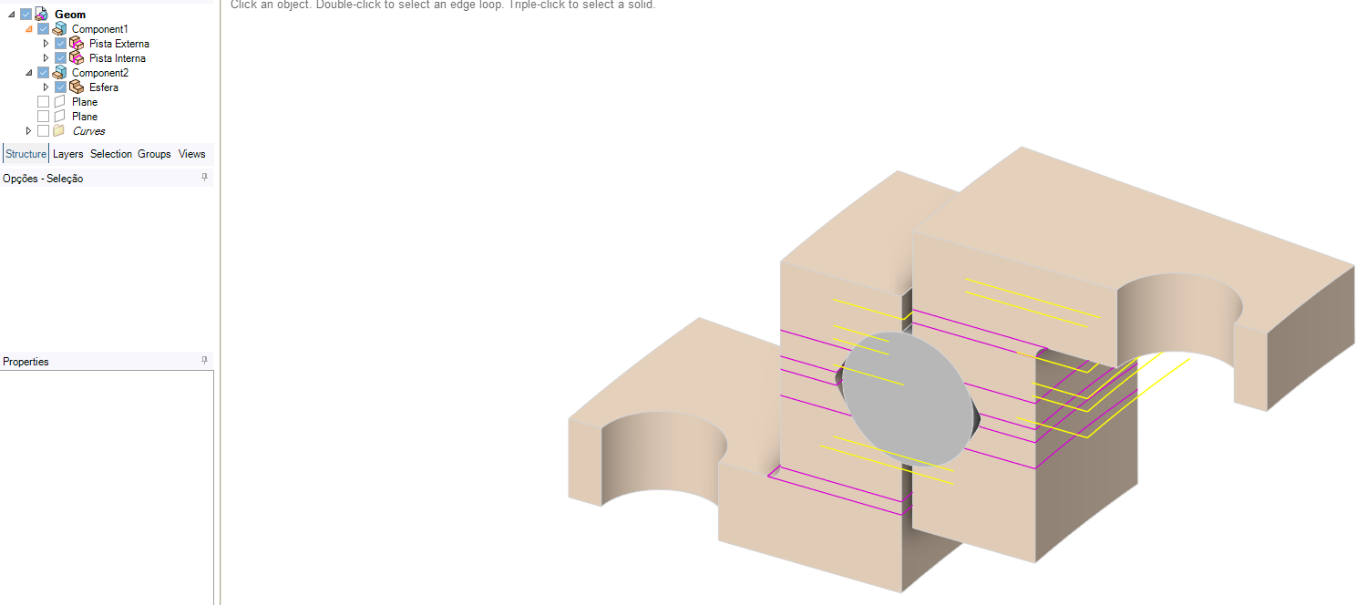
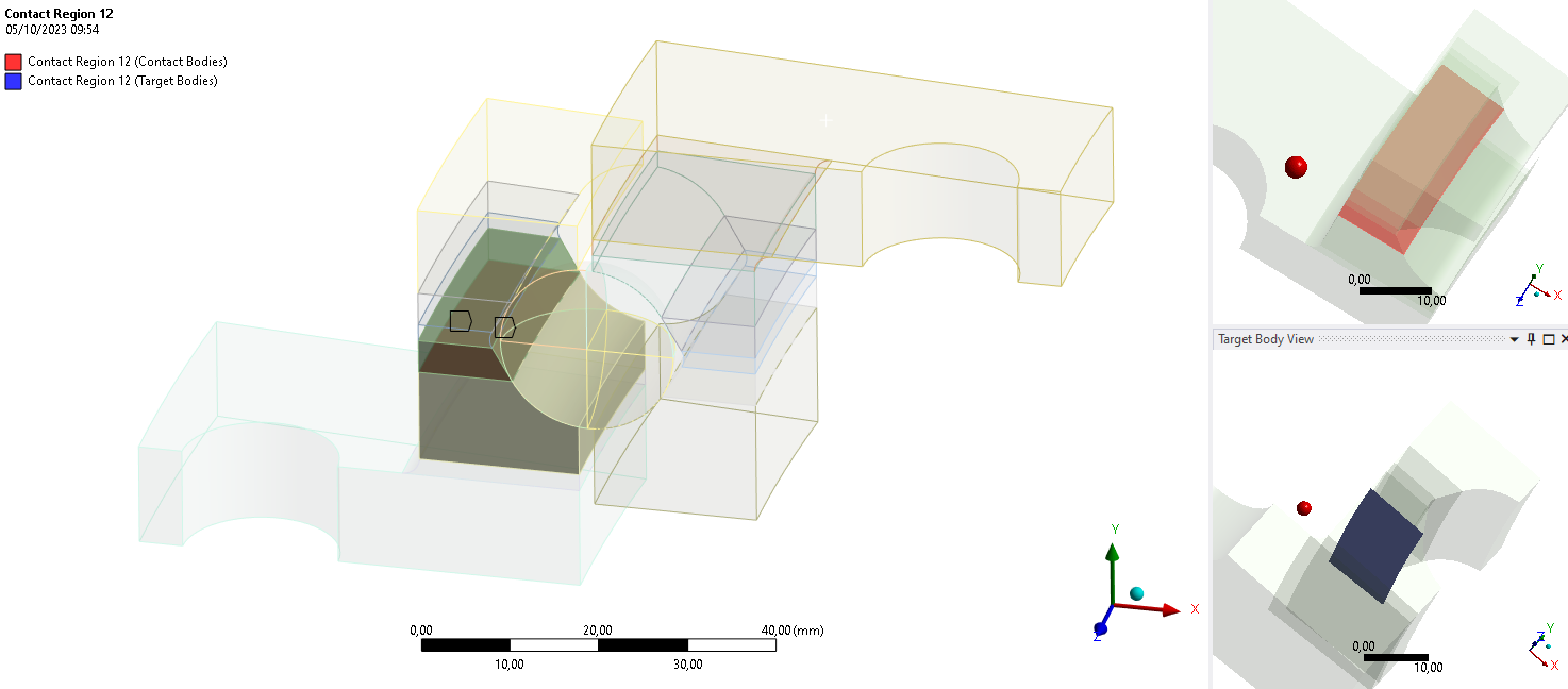
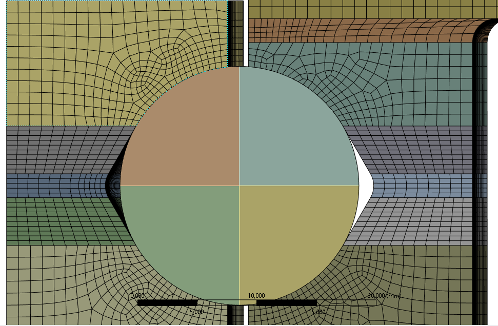
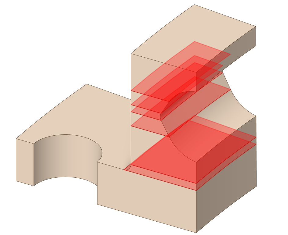
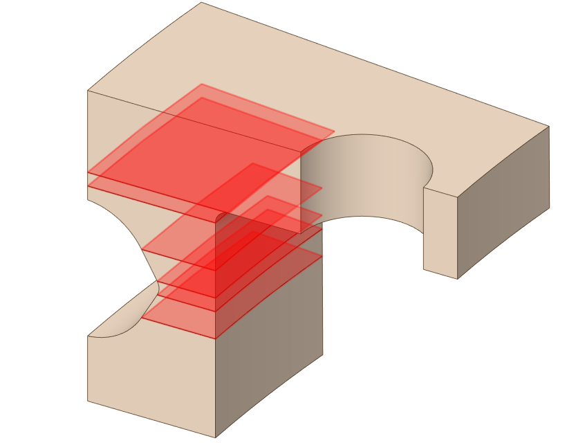
But now, although the individual components have share topology (see figure below with the exploding view), Mehcanical is creating contect between the parts of each component, which in my understanding should not be created if these parts have shared topology. This makes the nodes between the parts not coincident. Any thoughts on that?
-
-
October 6, 2023 at 8:01 am
Sampat Kumar
Ansys EmployeeHi Gabrial,
Please use the By Connection option to see if the shared topology has been performed or not. Always try to use share and unshare under the Workbench tab in the SpaceClaim. The pink color shows the shared one. Yes, if you have performed shared topology between the parts then it shouldn’t make contact between them. please verify the connected part in the SC again if they are shared or not and let me know.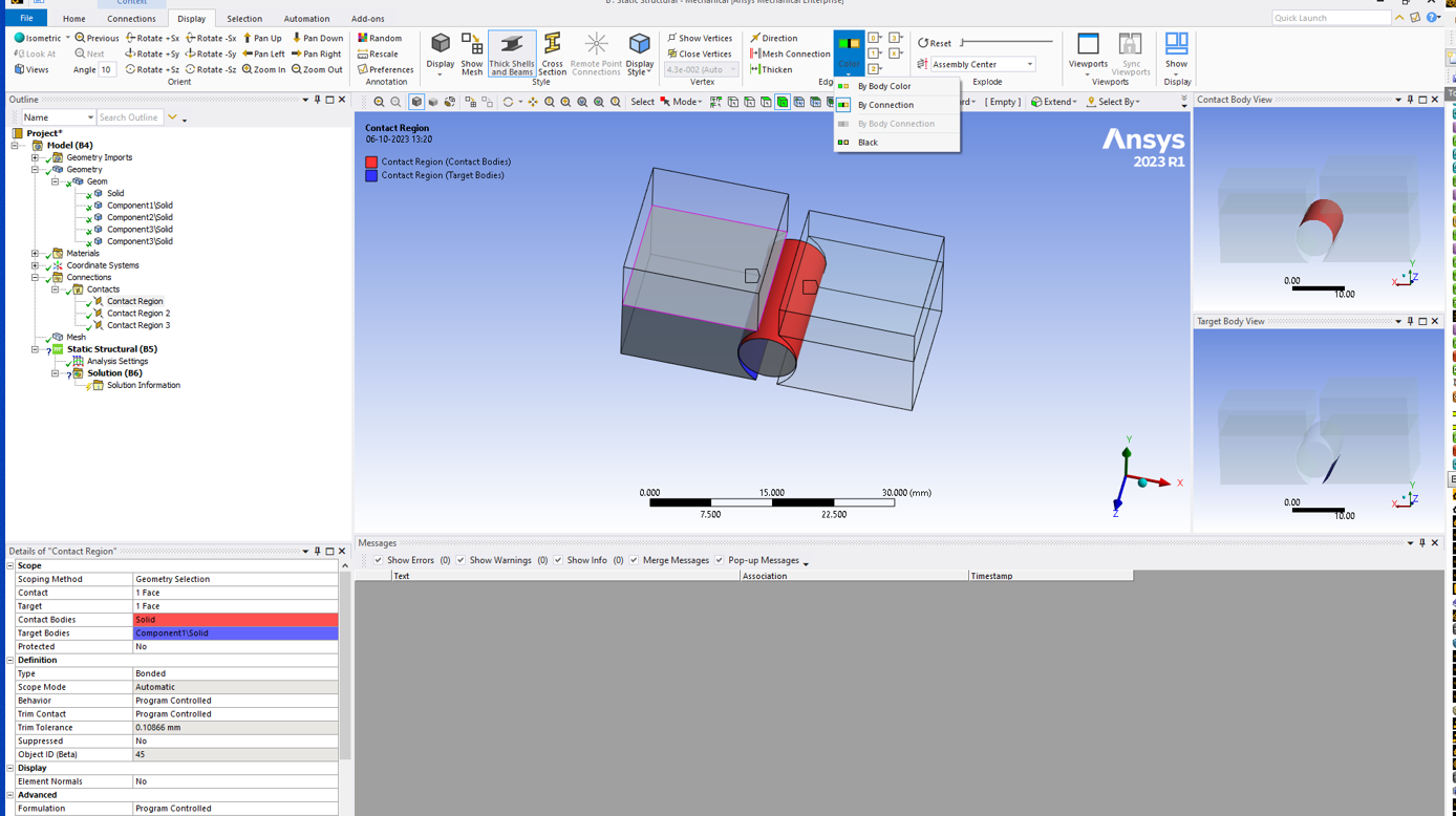
Regards,
Sampat-
October 10, 2023 at 1:20 pm
-
-
October 16, 2023 at 10:26 am
Sampat Kumar
Ansys EmployeeHi Gabriel,
Thanks for your patience,
It’s supposed to be updated in the mechanical. Just for information, I think you would have updated your model by selecting “update geometry from the source” in the Ansys Mechanical, after performing the share totpology option in the SC.
There is no need to perform the sharetopology individually. You can hide the ball and perform the Share topology option in the SC on the whole body part, then do the reverse visibility and perform the Share topology on the ball only.
After performing the Sahre topology, you can show all the body and click on the unshare (just to check which geometry parts are shared or not; don’t click on the green tick; it will perform the unshared operation) under the workbench tab to check which parts are shared or not. Then, click Update the geometry from the source in the mechanical. According to your geometry and shared topology operation, there should be two connections in the Ansys Mechanical. Please let me if you have chekced all these points and still facing this issue, then we can check others things also.
Regards,
Sampat-
October 20, 2023 at 6:08 pm
Gabriel Coêlho
SubscriberDear Sampat,
Your solution finally solved the problem.
Thank you.
-
October 22, 2023 at 11:51 am
Sampat Kumar
Ansys EmployeeHi Gabriel,
I appreciate the confirmation. Others who experience difficulties of such type in the future will benefit from reading this topic.
Regards,
Sampat
-
-
-
- The topic ‘Error when rigid body is defined’ is closed to new replies.


-
5094
-
1831
-
1387
-
1248
-
1021

© 2026 Copyright ANSYS, Inc. All rights reserved.

