-
-
October 15, 2018 at 1:08 pm
matthias.zeller
SubscriberHello,
I'd like to simulate the total displacement and total plastic strain of a part which suffers cyclic plastic strain. The force is alternating between 0 and a constant maximum force and it is applied slowly. So in every cycle the cross section of the part should be decreasing, the stress should be increasing and the plastic strain should be increasing.
My first idea was to simulate this as a static structural simulation using isotropic hardening. The problem is that the total displacement and plastic strain is not increasing due to the cyclic loading. When using a transient structural simulation the total displacement and plastic strain is increasing a little bit in every cycle. What is the difference? Is the decreasing of the cross section considered by the static and transient analysis? The part is quite complicated, so I prefer the static structural analysis. What is the best way to do this?
I use Workbench 19.
Thanks for your help
-
October 15, 2018 at 1:37 pm
Sandeep Medikonda
Ansys EmployeeHi maddes,
FEA results are based on True/Cauchy Stress-Strain. I would recommend you to look at the stress-strain response in a simple single element model for both cases along with cyclic loading. Peter has an excellent demonstration in this post.
Regards,
Sandeep -
October 15, 2018 at 2:44 pm
matthias.zeller
SubscriberHi,
thanks for your answer. First I tried a simple model, a tensile bar. No matter how many cycles I use the total displacement and (cumulative) plastic strain keep the same after the first cycle. What is the mistake?
I used static structural, isotropic hardening and large deformations switched off (similar result with large deformations switched on).
Attatched you can find some screenshots for the result after 10 cycles.
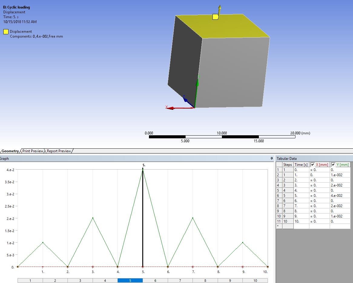
The load is as in the following screenshot:
The total displacement after 10 cycles:
The cumulative plastic strain (nlepeq) (same result like plastic strain):
-
October 15, 2018 at 3:56 pm
Sandeep Medikonda
Ansys EmployeeHi, Can you show what materials (stress-strain response) you are using and also confirm if you have large deflection on?
I am struggling a bit to understand the German words in your model. So I've just, checked this on a simple single element model:
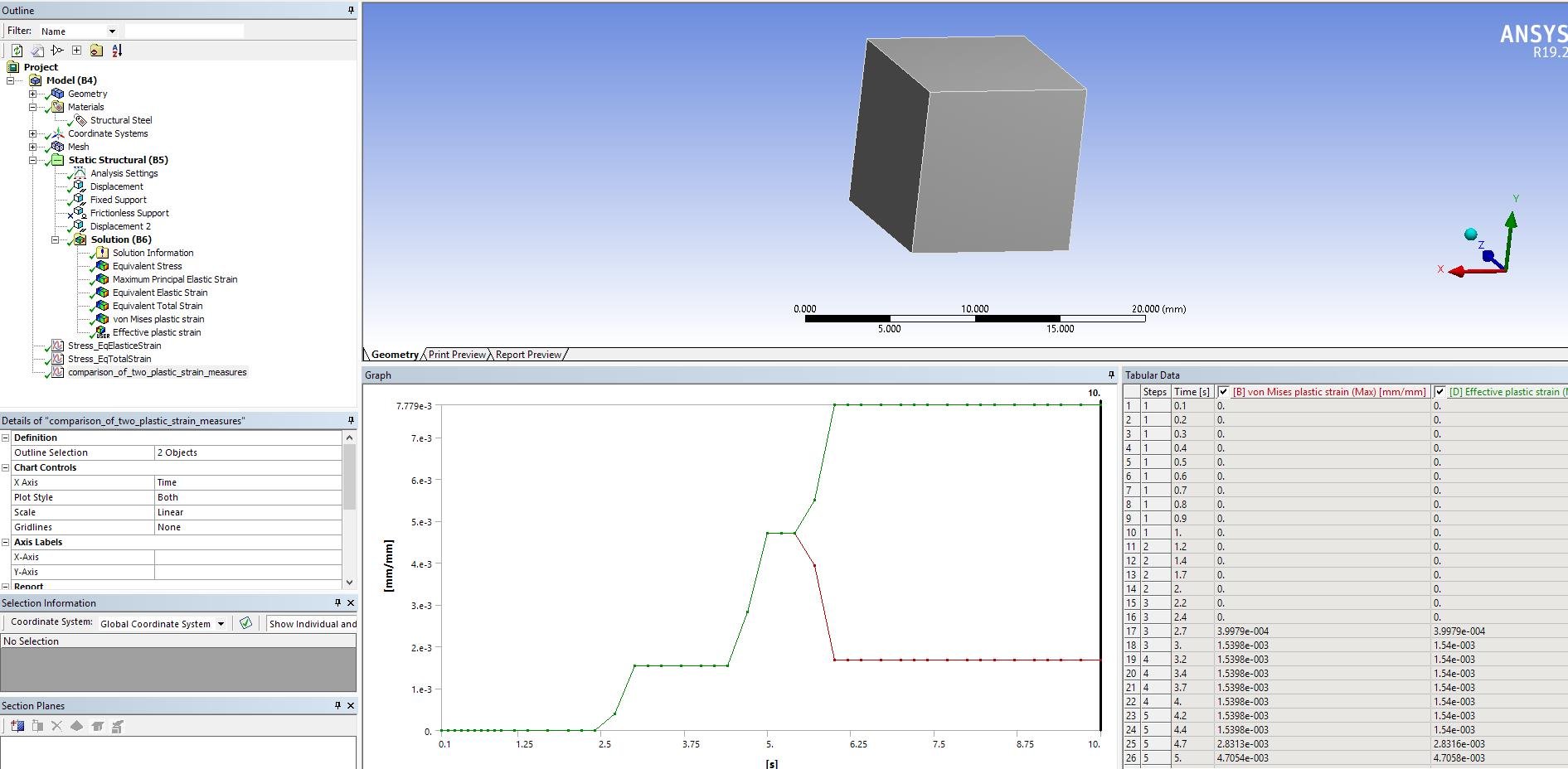
subjected to cyclic loading:
and I see a clear difference between the von-mises plastic strain and the effective plastic strain:
Hope this helps.
Regards,
Sandeep
Best Practices to post on the Student Community -
October 16, 2018 at 9:52 am
matthias.zeller
SubscriberThe difference between your model and my model is that I have used a changing force (between 0 and maximum force) as a load and you used a changing displacement.
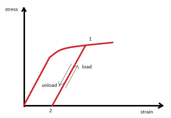
I think I had/have a misunderstanding with the physics. You said ANSYS calculates the true stress/strain. Is it right that the material behaves like the following picture when using isotropic hardening and a constant maximum force in every cycle? So in the first cycle the cross-sectional area decreases and a balance between stress, cross-sectional area and strain is reached (Point 1)? In the next cycles the material is changing between Point 1 and Point 2 in the stress-strain curve? In this case ANSYS did the right job in the simulation I did.
I would like to know the total displacement/plastic strain of my part after 10 cycles. There has to be an increasing elastic strain in every cycle (ratcheting?). So do I need to model it with Chaboche? How do I have to do it?
-
October 16, 2018 at 11:27 am
-
- The topic ‘Cyclic elastic-plastic simulation’ is closed to new replies.


-
4607
-
1510
-
1386
-
1209
-
1021

© 2025 Copyright ANSYS, Inc. All rights reserved.

.jpg?width=690&upscale=false)
.jpg?width=690&upscale=false)
.jpg?width=690&upscale=false)


