-
-
September 26, 2023 at 3:48 pm
-
September 26, 2023 at 7:21 pm
Vaman Shenoy
Ansys EmployeeHello Karthik,
Thanks for reaching out.
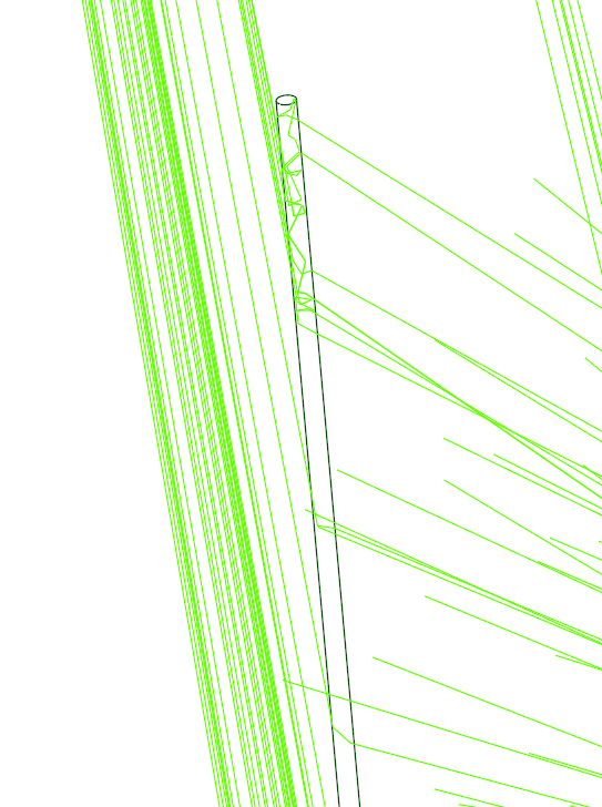
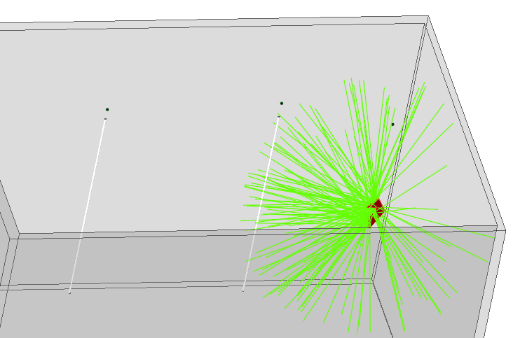
Based on your explanation, I am guessing that you have designed 2 optical fibers and are trying to use a light source at one end expecting it to pass the light through the fiber/light pipe. It seems like you are using Interactive Simulation here.
The position of the source and type of source used does not seem to be very clear from the image. Would it be possible to share some more images of the setup and also the details of the kind of source and/ or the sensor you are using for this application?
Thanks!Vaman
-
September 28, 2023 at 10:26 am
Karthik Buddala
SubscriberHii, Thank You for your reply. In this below image, You can see two optical fibers, Actually total internal reflection is not happening in these fibers. If i will be provided with sample properties to make it work as a optical fiber it would be helpful. I'm using radiance sensor. and Direct simulation.
-
- The topic ‘Optical Fiber sensor’ is closed to new replies.


-
4683
-
1565
-
1386
-
1242
-
1021

© 2025 Copyright ANSYS, Inc. All rights reserved.


