-
-
October 11, 2018 at 9:42 am
jamesgr
SubscriberHi everyone,
I would like to use BladeGen for a design optimisation study of centrifugal pumps. Using the GUI initially, I can export a BGI file, define variables, and use the batch command to create new geometries from the BGI file.
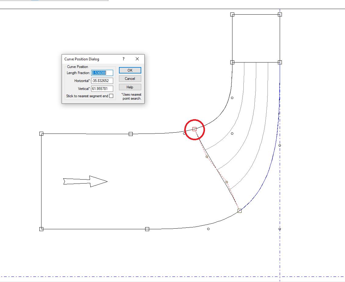
However, there is a problem when defining the control points of the LE. Namely, in the GUI, the end control points are such that they always lie on the hub and shroud curves. You can even define a length fraction that specifies how far along the streamwise direction of the hub and shroud curves the LE control points are.
However, in the BGI file, the control points of the LE are not constrained such that the end points lie on the hub and shroud surfaces. Instead, these points are strictly defined by their Z-R values.
Begin LeadingEdgeCurve
New Segment
CurveType=Bezier
UpstreamControl=Free
Begin Data
( -7.669881059,23.35438893 )
( -15.79710000,30.48810000 )
( -25.22529274,37.83793911 )
( -32.58647974,44.66386003 )
End Data
DownstreamControl=Free
End Segment
End LeadingEdgeCurve
This leads to difficulties when I change the location of the control points for the hub and shroud or the LE curve, as these end points no longer lie on the hub and shroud surfaces, which leads to issues when exporting curve profiles to TurboGrid. Is there any way to ensure these end points are strictly constrained to lie on the hub and shroud surfaces in the BGI file?
Thanks for any help or advice you can give!
James -
October 12, 2018 at 12:20 pm
jamesgr
SubscriberNo one?
I've managed to come up with a workaround by creating a simple Python script. The function takes in the hub or shroud Bezier curve control points and a length fraction and creates a Bezier curve. This Bezier curve is then discretised into a user-defined number of points. The function then outputs these points (as well as the LE point) to be used for a spline representation of the hub or shroud.
The workaround is very imperfect, but it gets the job done (particularly if the number of discretised points is large). However, I would still be very interested if anyone else has any advice or tips.
James -
November 23, 2019 at 4:42 pm
transonic
SubscriberHey James,
When you scripted BladeGen originally, were you able to activate parameters for use in DesignExplorer or did you have to run the optimization loop outside workbench and drive it via workbench scripts?
-
November 23, 2019 at 6:00 pm
transonic
SubscriberCan you explain a bit more how you used the batch command to create new geometries? Or what your overall workflow looked like?
Thanks
-
November 25, 2019 at 10:10 am
jamesgr
SubscriberHello,
My workflow was defined outside of workbench. That is, I created a template script for each ANSYS package (BladeGen, TurboGrid, and CFX) and using Python filled in the necessary fields for the templates and ran each package from command line. I defined a function which took in an array of numbers which defined the design variables and output the quantities of interest (e.g. efficiency). I could then use off-the-shelf optimisers or my own to perform optimisation.
For BladeGen in particular, once I had a baseline geometry with all of the design parameters (e.g. blade angle distributions, blade thickness distributions, etc.), I created a BGI file. In this BGI file, all I had to do was to change the numeric values for each of the design parameters when I wanted to create a BGI file for a new geometry. Once I had the new BGI file, I could create the TurboGrid profiles using the BladeBatch executable. In my case, this was done by running the following:
ANSYS_FolderaisolBladeModelerBladeGenBladeBatch.exe BGI_FolderNew.BGI -TG Folder_To_Write_To
I hope this helps!
James
-
- The topic ‘Scripting BladeGen using BGI file: LE control points on hub and shroud’ is closed to new replies.
-
5899
-
1906
-
1420
-
1306
-
1021
© 2026 Copyright ANSYS, Inc. All rights reserved.
