-
-
September 15, 2023 at 6:48 pm
Raúl Sotillo
SubscriberHello everyone!
I am trying to simulate a planar SOEC (Solid Oxide Electrolyser Cell) where the inlet is H2O, to produce H2 (cathode) and O2 (anode) at 800ºC (1073K). I am using the Fuel Cell and Electrolysis module, and defining it for Electrolysis. I am using ANSYS 2022.
The layers I am using are, from top to bottom (and represented on the figure).
- Cathode Interconnector
- Cathode Channel (defined by the gap in the cathode interconnector)
- Cathode Gas Diffusion Layer
- Cathode Active Layer
- Electrolyte
- Anode Active Layer
- Anode Gas Diffusion Layer
- Anode Channel (defined by the gap in the anode interconnector)
- Anode InterconnectorIt is a simple geometry, 20x20cm, with straight channels. The channels are flowing in cross flow, so the direction of the anode channel is perpendicular to the direction of the cathode channel.
I have not defined my own source terms, but instead, and according to the ANSYS Guide, I have selected where each one of them takes place (in which area) and I expect those terms to change accordingly for an Electrolyser.
Also, the voltage I am defining it with values of +1.3V for the tab in the Anode, and 0V for the tab in the Cathode, the upper and the bottom parts of the interconnectors, defining like that the voltage difference. I've set the OCV Voltage to +0.84V.
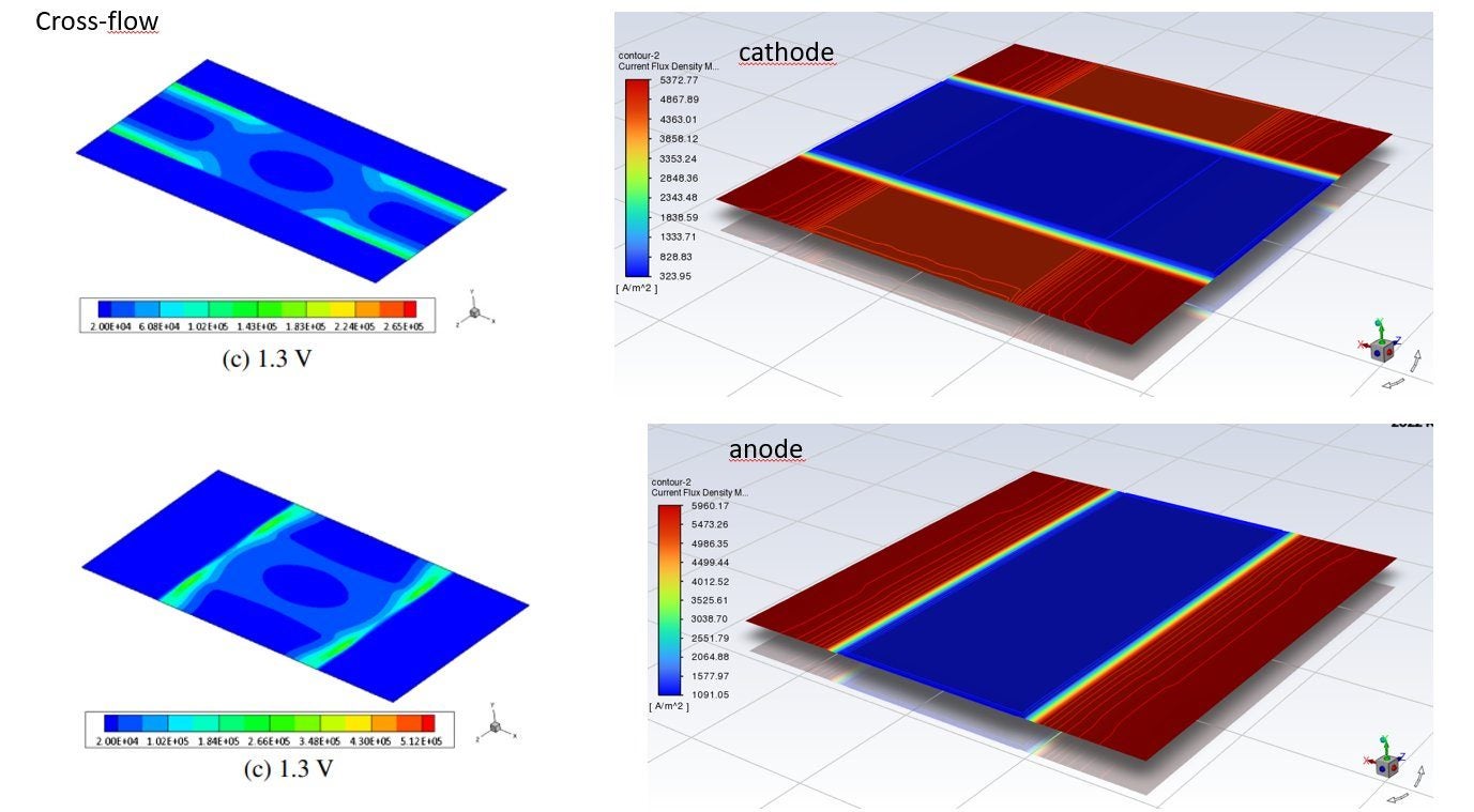
Nevertheless, when I run the simulation, and even though it successfuly generates H2 and O2, I get very high values for the Current density (A/m2) in areas where it should be low. I am trying to replicate and compare with the following article: http://dx.doi.org/10.1016/j.apenergy.2014.04.104
The current should have a different profile. Attached you can find the image, comparing at left the article results and on the right my results. Also, my values are clearly different.
- Am I considering right the signs on the source terms? Should I edit something for the electrolysis mode in this Module?
- I am sure there has to be a problem with the sign of the values (+/-) somewhere. Anyone has any clue?
- Are there any boundary condition I haven't set up?Also, the quantity of H2 and O2 produced ans the Temperature are very much dependent on the Initial conditions for simulating... Making the results not very trustable.
I am 3 weeks away of presenting my thesis and a small help in this matter would mean so much to me. I could also menction that help on my thesis :)
-
September 26, 2023 at 6:06 pm
Aleksey Gerasimov
Ansys EmployeeHello Raul,
The main confusion for SOEC comes from a different definition of anode and cathode between fuel cells and electrolyzers. We have a chapter in the User Guide that explains this point. Unlike in the PEMWE and AEC models where notation is conventional, The SOEC notation inherited the very same notation as the SOFC. Naturally, it might create some confusion for the placement of potential boundary conditions.
The best way, to look into this issue consistently is by looking at the location of the OER (Oxygen Evaluation Reaction) and HER ( Hydrogen Evaluation Reaction). Please also consider prescribing voltage directly in the FC&E panel. The software will apply the voltage consistently, and then when everything becomes clearer, you can change to prescribing the potential boundary conditions directly at terminals.
Hope this helps and please let me know if you have any further questions.
Please note that the current densities in the order of 0.5 A/cm2 (5000A/m2) are perfectly achievable in solid-oxide electrolysis and fuel cells.
Kind regards,
Aleksey.
-
September 27, 2023 at 5:21 pm
Raúl Sotillo
SubscriberHello Aleksey. Thanks so much for the answer. This solves a few months of doubts about this; in the guide, it was somehow explained but I couldn’t properly catch it. I also dropped a question on that topic here.
How can I set up the voltage from the PC&E Panel? I can only see how to set up the OCV, which in my case I’ve set up to +0.84V. And then I always indicate that on the Boundary Conditions.
Kind regards,
Raúl -
December 11, 2023 at 8:29 pm
Ali Hussein
SubscriberDear Mr. Gerasimov,I am a master's student working on the simulation of PEM water electrolysis , However, I am encountering some issues and kindly request your assistance. After activating the Fuel Cell and Electrolysis Model(3), I have located the Tabs, flow channels, current collectors, membrane, catalysts, and diffusion layers in the model. For the inlets, I am using mass flow rate, and the visible species are H2O, oxygen, and hydrogen. Unfortunately, I am having trouble with the H2O being in a vapor state when I need it to be in a liquid state. I have attempted to edit and modify the multiphase(VOF) and edit the species, but the boundary condition DOESN'T displays hydrogen nor being produced.I would be grateful for any recommendations or assistance you could provide me with. Thank you for your time and consideration.Best regards,
-
-
September 26, 2023 at 6:18 pm
Raúl Sotillo
Subscriber -
September 29, 2023 at 2:21 pm
Aleksey Gerasimov
Ansys EmployeeHello Raul,
Yes, you are right. For the Unresolved SOFC/SOEC approach you can specify voltageor current b.c.'s directly in the FC panel, but the FC&E module does not offer such possibility yet. I have logged an enhancement request for this issue.
For the time being, please anchor the voltage to 0V at the hydrogen evolution side (Cathode - in conventional notation, Anode - in the FC&E panel), then please set the required voltage value, say 1.4V at the oxygen evolutoin side ( Anode - in conventional notaion, Cathode - in the FC&E panel)
Hope this helps,
Aleksey.
-
September 29, 2023 at 3:09 pm
Raúl Sotillo
SubscriberHi Aleksey, Thank you for the answer, it helps a lot.
The program calculates V_total = V_cathode (conventional, H2 side) - V_anode (conventional, O2 side). Therefore, when I include a positive value for the potential, then my V_total is negative. This can generate problems since my OCV is designed as positive (+0.84V).
Shall I consider a negative voltage of, let's say, -1.4 V in the O2 side? Maybe I should state that the OCV is -0.84V?
I hope you can hep me with this matter.
Thank you,
Raúl
-
November 16, 2023 at 12:08 pm
Raúl Sotillo
SubscriberGood afternoon Aleksey.
Some time ago I asked you another question about the topic. It is in the previous answer.
Did you have time to take a look at it?
Thank you,
Raúl -
December 8, 2023 at 4:27 pm
Raúl Sotillo
Subscriber-
December 11, 2023 at 8:40 am
Aleksey Gerasimov
Ansys EmployeeHello Raul,
The evaluation of the reference current densities, anodic/cathodic transfer coefficients, and the associated reference molar concentrations, is something that comes from measurements for materials and for simplified fuel-cell that is made out of them, for example, a button fuel cell. There are different means on how these quantities can be measured and assessed. For example, through the assessment of the Tafel slopes. The concentration exponent is something that can be evaluated from further tests that are carried out at different molar concentrations. Suppliers of these parts, typically, have this data available.
Kind regards,
Aleksey.
-
January 23, 2024 at 10:17 pm
Raúl Sotillo
SubscriberHello Aleksey.
I still can't find a solution for this. My Current Density values make sense, and the temperature remains rather constant; but the species values that I get in the solution are highly dependent on the initial values: if I initialise with 95% H2O and 5% H2 in the cathode fluid areas, and with 10% O2 in the anode fluid areas, for example, I obtain a different solution that the one I get if I simulate with different initial values. Both solutions converge. Any recommendations or comments?
Thank you.
Raúl -
January 24, 2024 at 3:36 pm
Aleksey Gerasimov
Ansys EmployeeHello Raul,
If the boundary conditions and the model settings are identical, then the corresponding solutions should become identical eventually. There are a couple of points to consider:
1) Convergence assessments. Please ensure that the solutions are deeply converged not only in terms of residuals' values, but also in some monitors for variables and parameters that are critical to fuel-cell operation: fuel and oxygen utilization, minimum and maximum values for molar fractions in the reaction zones, minimum and maximum temperatures. Please ensure that the double-precision solver is used and that the convergence criteria is lifted from 1e-3 to "none" for all solved equations
2) Please check the presence of inert non-reacting species in the reaction zones, such as nitrogen and water vapour on the "wrong" side. These species can get initialized/patched within the porous layers and it might be difficult for them to get out of there. They can easily reduce the usage of the cell active area and change the outcome of the simulation.
Hope this helps,
Aleksey.
-
January 25, 2024 at 7:48 pm
Raúl Sotillo
SubscriberThank you Aleksey.
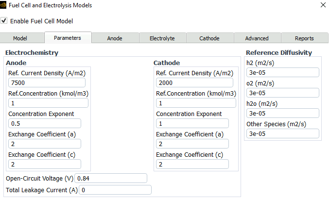
I've checked that. I still get values of the Current Density in the Anode much higher than the values they should be. I am using an article as a reference, that uses 7500 A/m2 for the Cathode exchange current density and 2000 A/m2 for the Anode exchange current density. I found it very strange that the predefined measure was 20 A/m2 in ANSYS. In the article, they use the predefined materials as well.
Could you help me with this matter?
Raúl
-
-
-
December 1, 2023 at 1:35 pm
Syafawati Hasbi
SubscriberHi Aleksey, I found through manual as attached there are two ways to get the current density, it is either on the console, or by surface integral of current density at y direction/ area. I got different current density using both approach, console (1.6A/cm2) and by surface integral (0.049A/cm2) for 0.01m2 fuel cell. Which one should I choose?
-
December 11, 2023 at 8:43 am
Aleksey Gerasimov
Ansys EmployeeHello Syafawati,
Please ensure that you are using the surface-normal component of the current density. It would also help to see what is being compared exactly and the locations where these values are being assessed.
Kind regards,
Aleksey.
-
-
December 11, 2023 at 8:50 am
Syafawati Hasbi
SubscriberI took the surface integral of y current flux density at cath terminal over area of cathode terminal. Did the value of current density depends on which area that we take? How about the current density at the console? Is that the average current density of the overall fuel cell? Thank you.
-
January 24, 2024 at 3:39 pm
Aleksey Gerasimov
Ansys EmployeeHello Syafawati,
It's the terminal's surfaces, where we apply potentiostatic (prescribed voltage) boundary conditions or galvanostatic (prescribed current) boundary conditions. These surfaces matter for assessment of total current that flows through them.
Kind regards,
Aleksey
-
-
- The topic ‘SOEC (Solid Oxide Electrolyser Cell) – Some questions in Simulations’ is closed to new replies.


- air flow in and out of computer case
- Varying Bond model parameters to mimic soil particle cohesion/stiction
- Eroded Mass due to Erosion of Soil Particles by Fluids
- I am doing a corona simulation. But particles are not spreading.
- Issue to compile a UDF in ANSYS Fluent
- Guidance needed for Conjugate Heat Transfer Analysis for a 3s3p Li-ion Battery
- JACOBI Convergence Issue in ANSYS AQWA
- affinity not set
- Resuming SAG Mill Simulation with New Particle Batch in Rocky
- Continuing SAG Mill Simulation with New Particle Batch in Rocky

-
4502
-
1494
-
1376
-
1209
-
1021

© 2025 Copyright ANSYS, Inc. All rights reserved.


