-
-
September 14, 2023 at 12:39 pm
Caleb Wood
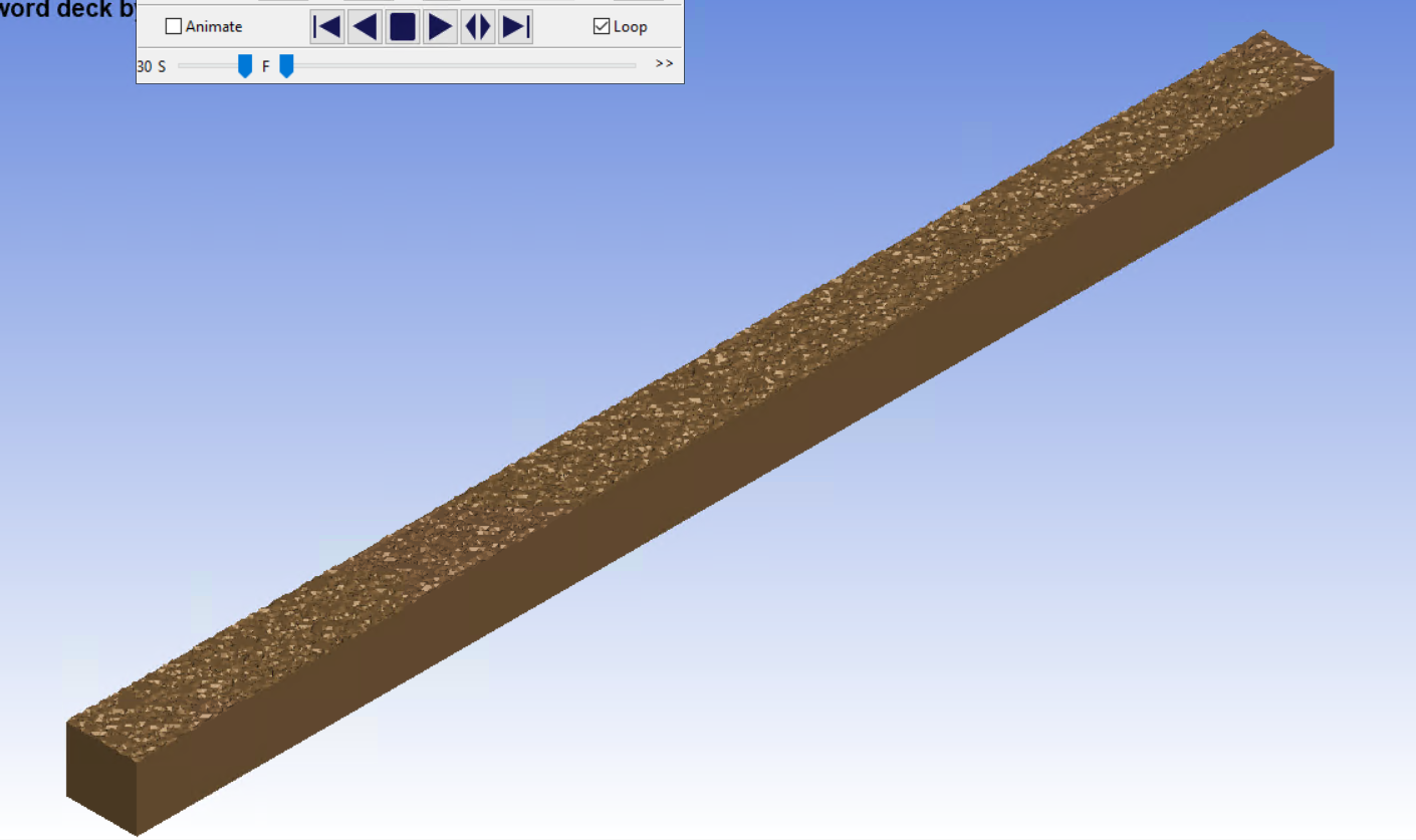
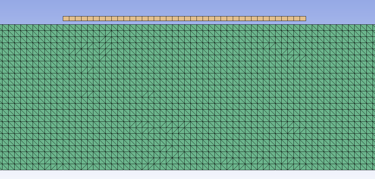
SubscriberHello, I am making a wave flume using ICFD and it works well except for one issue, which is the initial water surface is not uniform (flat). I thought this may be a meshing issue so I made a model with an ultra fine mesh but it did not resolve it. The mesh is uniform throughtout (each element is the exact same size) and all nodes are merged. It also consists of an upper air portion not pictured. The model makes waves as expected however the initial noise in the water disrupts it. Does anyone know why this is occuring? Thank you.
-
September 15, 2023 at 10:42 pm
Reno Genest
Ansys EmployeeHello Caleb,
Which solver are you using? Have you tried with the latest R14 MPP double precision solver? You can download it here:
https://ftp.lstc.com/user/download_page.html
username: user
password: computer
Have you tried decreasing the timestep?
Here are 2 examples with wave generation:
https://www.dynaexamples.com/icfd/basics-examples/wave_gen
https://www.dynaexamples.com/icfd/advanced-examples/pillar
Let me know how it goes.
Reno.
-
September 18, 2023 at 1:29 pm
Caleb Wood
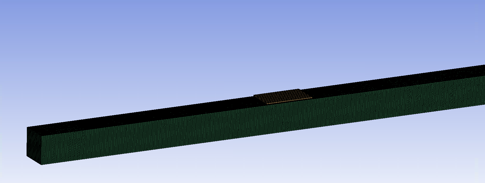
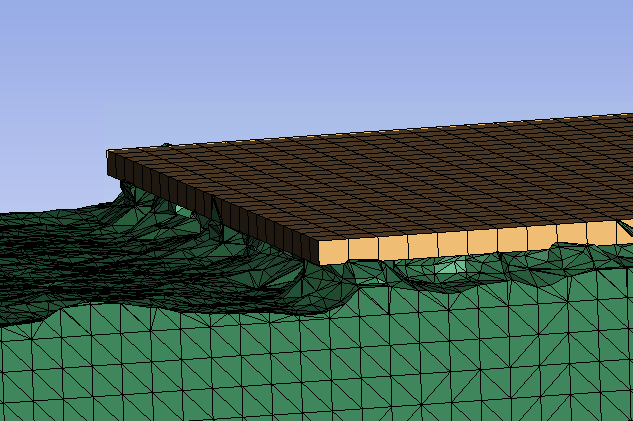
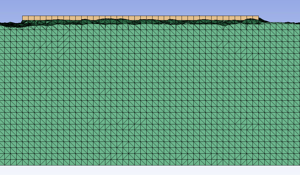
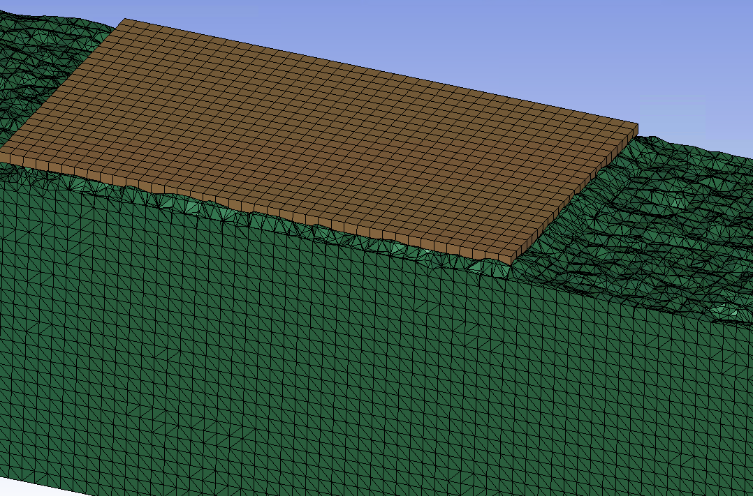
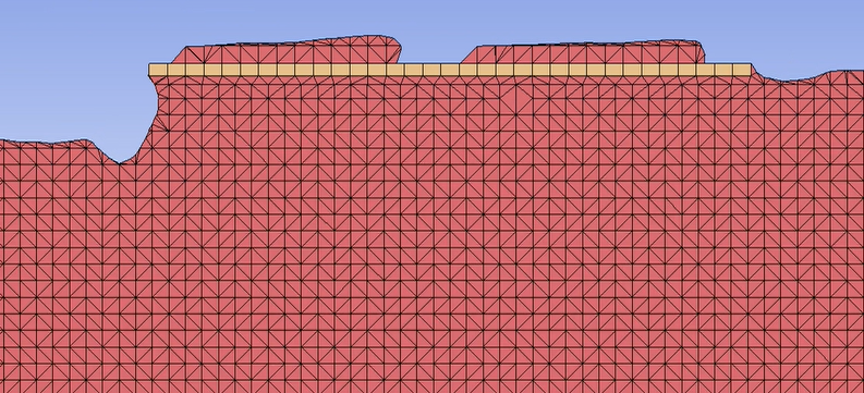
SubscriberI corrected this issue (I was meshing the problem incorrectly) but now I have run into another issue. I have a rigid plate placed slightly above the water surface, and it appears that the water is getting stuck to the underside of the plate (see photos). I am using a timestep of 0.01 and two-way strong coupling (OWC is set to 0 in ICFD_CONTROL_FSI and I am using an implicit solver). I have sifted through quite a few examples seen online and everything in my model appears to be consistent with those models, so I am unsure why this is occuring. Any insight on the issue would be greatly appreciated.
Thank you,
Caleb
-
-
September 18, 2023 at 10:50 pm
Reno Genest
Ansys EmployeeHello Caleb,
What is the problem exactly? Water is stuck under the plate? Is the rigid plate allowed to move or is it fully constrained? Do you have constraints on the rigid plate using *MAT_020 CMO and CON1 and CON2 parameters? If the rigid plate is fully constrained, then you won't have motion of the plate and the water will be stuck under the plate.
Also, what is the mechanical timestep vs the fluid timestep? Make sure the Mechanical timestep is smaller than the fluid timestep; this way, the fluid timestep will be equal to the mechanical timestep.
You can try changing the timestep and see the effect.
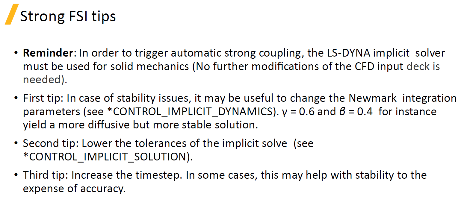
Here are more tips from the training material:
You can find this training on the Ansys Learning Hub (ALH):
https://jam8.sapjam.com/groups/QyHAlhciRCZ0Xt6xKZ2MHi/overview_page/jPMouxqQ2AOP6jVZLBMZCl
Let me know how it goes.
Reno.
-
September 18, 2023 at 11:17 pm
Caleb Wood
SubscriberI am experimenting with the timesteps now and I'll let you know how it goes. Here is some additional information in the mean time:
The rigid plate is constrained in all directions using CMO +1, CON1 7, CON2 7. There is an initial air gap between the plate and the still water surface measuring 0.015 meters. The rigid plate is subjected to a wave train with each wave measuring 0.15 meters in height and a length of 2 meters. This means that between waves the plate should not have any water in contact with it for a few split seconds.
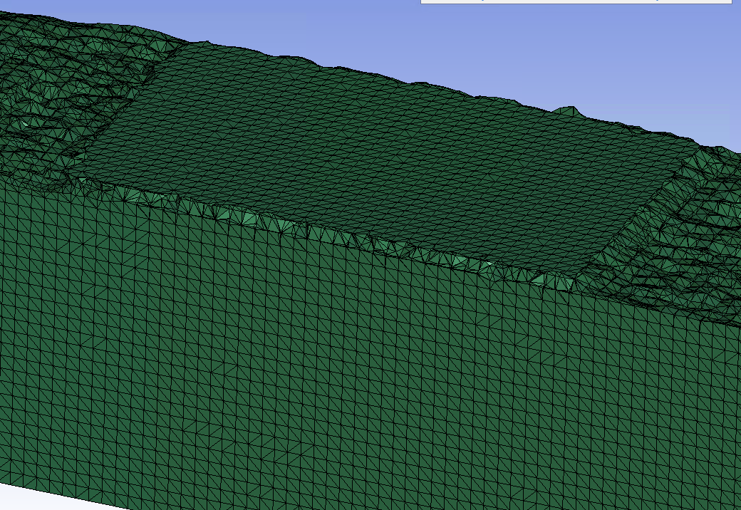
I have attached more images which hopefully show the model more clearly.
Thank you,
Caleb
The water here is stuck to the underside of the plate, when I believe it should be a constant level with the surrounding water.
-
-
September 18, 2023 at 11:26 pm
Reno Genest
Ansys EmployeeHello Caleb,
If you remove the rigid plate, do you see the expected behavior for the free surface problem and the waves?
Do you have surface tension defined?
Could you simplify this model and run in 2D? Here is an example:
https://www.dynaexamples.com/icfd/basics-examples/wave_gen
With a 2D model, you could run faster and troubleshoot quicker.
Reno.
-
September 19, 2023 at 8:15 pm
Caleb Wood
SubscriberWhen the plate is removed the waves porpagate as expected. Surface tension is set to 0 in the ICFD_MAT card. I simplified the model to 2D and the same issue remains, I even tried using an elastic material for the plate and nothing changed. The below image shows where I am currently at, and I am unsure of what else to try.
-
-
September 19, 2023 at 8:32 pm
Reno Genest
Ansys EmployeeHello Caleb,
What are you looking for? What kind of results? If the rigid plate is fully constrained and does not move, why not have a boundary in the fluid domain to represent the rigid plate?This way you wouldn't need to do an FSI simulation and you would avoid this problem.
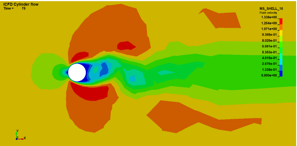
For example, this cylinder flow example; the cylinder is not meshed; only the boundary is included:
https://www.dynaexamples.com/icfd/basics-examples/cylinder_flow
Let me know if this helps or not.
Reno.
-
September 19, 2023 at 8:49 pm
Caleb Wood
SubscriberI am trying to replicate results from the following paper in a 3D domain: https://doi.org/10.1016/j.apor.2011.08.002
The reason for replication is to serve as a proof of concept for my future problem, which is modelling a portion of a real-world wharf and subjecting it to wave loadings. The wharf is likely to be modelled as elastic, so the method you mentioned would not work for my full scale problem. It might, however, work to verify the method. I will look into it and come back when I have results.
Thank you for all the help,
Caleb.
-
-
September 19, 2023 at 9:58 pm
Reno Genest
Ansys EmployeeHello Caleb,
Do you have the following in your model?
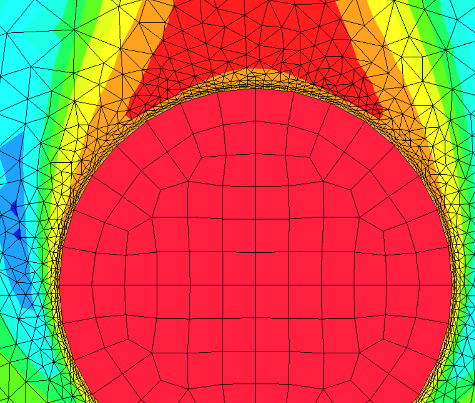
- *ICFD_BOUNDARY_FSI and *ICFD_BOUNDARY_NONSLIP on MSMESH parts (fluid parts) around the rigid plate?
- A boundary layer around the rigid plate? *MESH_BL.
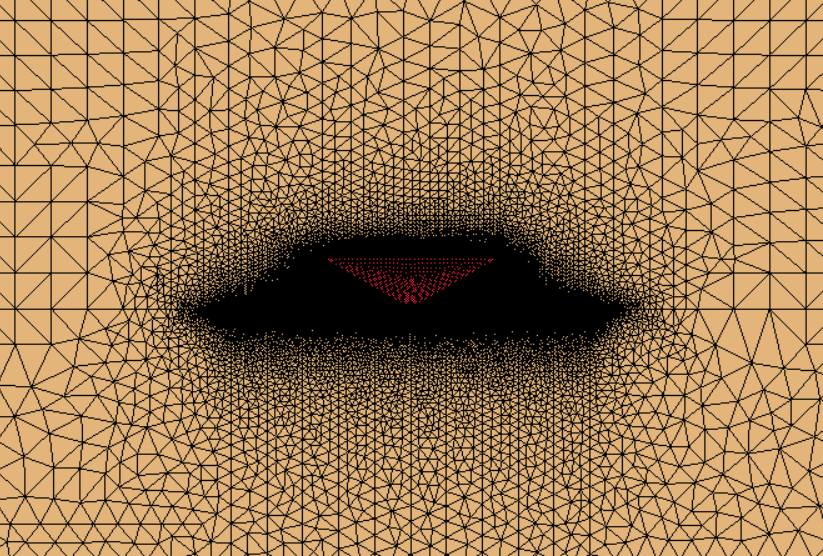
I think your fluid mesh is too coarse for the FSI to work properly and you should include a boundary layer. In the following 2 examples:
https://www.dynaexamples.com/icfd/basics-examples/weakfsi
https://www.dynaexamples.com/icfd/intermediate-examples/slam3
The fluid mesh has a boundary layer and it is much finer than the structural mesh:
I would try to reproduce one of these 2 examples first. Create your own mesh and see if you can reproduce the results with a coarse fluid mesh. Then, refine the mesh, add a boundary layer and see what you get.
At last, I would also try without constraints on the rigid plate and see what you get. But, I think a finer mesh will help prevent the leakage.
Let me know how it goes.
Reno.
-
September 22, 2023 at 12:37 pm
Caleb Wood
SubscriberHi Reno,
I was able to successfully verify the problem in 2D. My issue was the mesh quality around the contact point. By using MESH_BL and refining the mesh around the point of interest, I was able to solve all my issues.
Thank you for all the help,
Caleb.
-
September 22, 2023 at 6:34 pm
Reno Genest
Ansys EmployeeHello Caleb,
Sounds good! Thank you for letting us know what fixed the problem.
Have a great day!
Reno.
-
- The topic ‘ICFD water suface not initially flat’ is closed to new replies.


-
4959
-
1639
-
1386
-
1242
-
1021

© 2026 Copyright ANSYS, Inc. All rights reserved.

