-
-
September 14, 2023 at 12:10 pm
Zijian Hua
SubscriberHello, friends
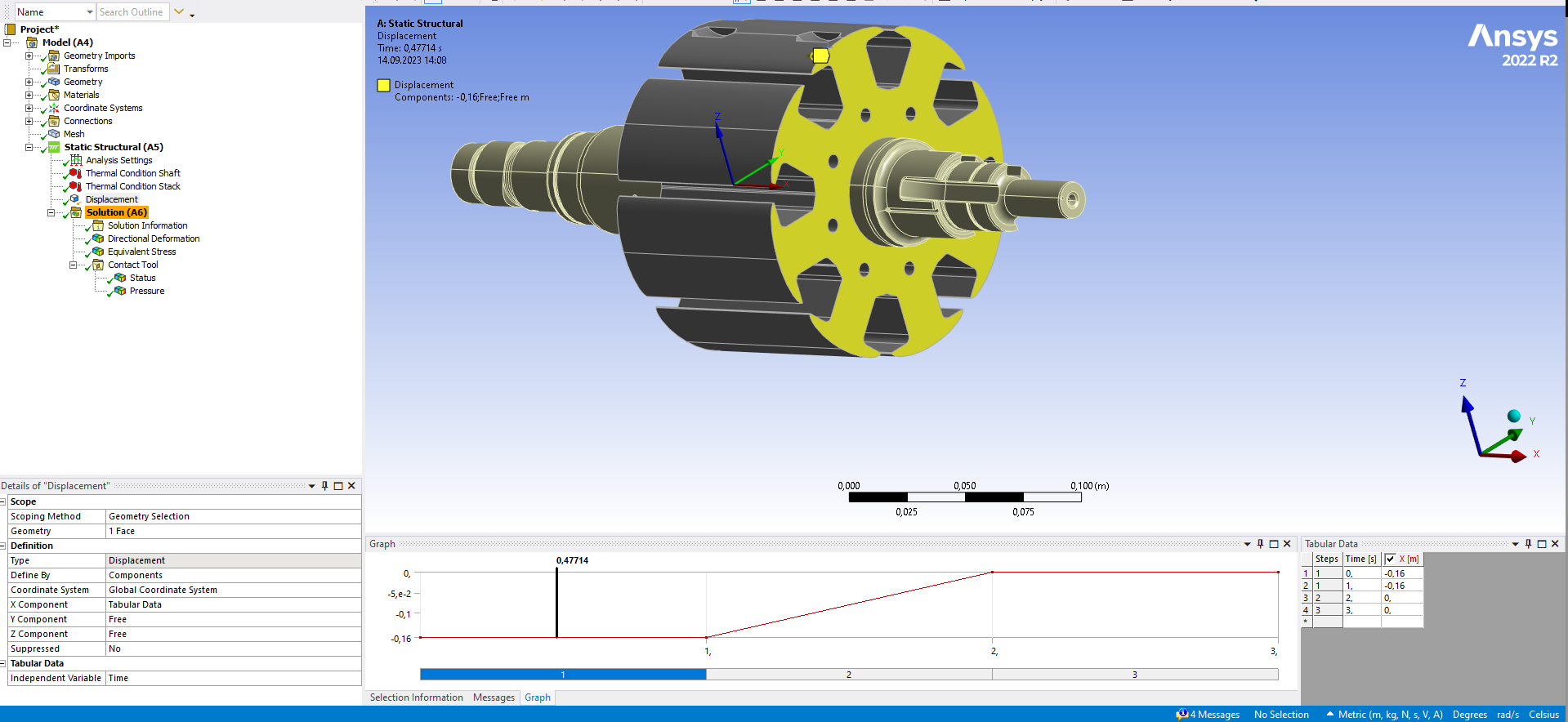
My simulation is about interference fit. A cooled shaft is inserted into a heated and expanded stack.
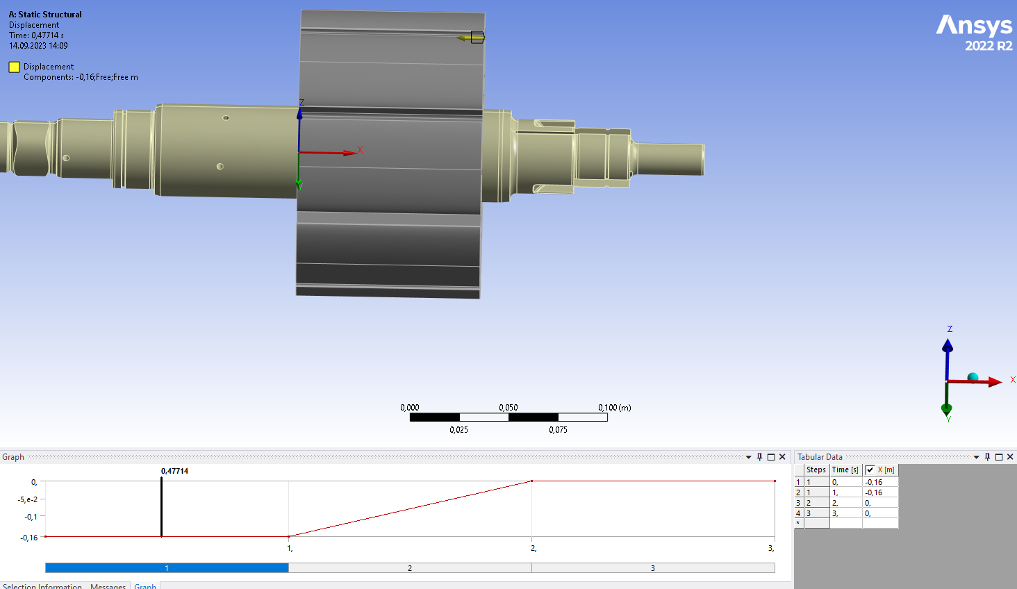
I selected a surface of shaft and put a displacement. Its starting position should be at 0.16m in the negative direction of the x-axis, and then gradually insert the laminations.
The Coordinate System is chosen as Global Coodinate System. In Analysis Settings, there are 3 time steps. But in Solution Animations the shaft doesn't move as I expected. Â
What is the problem about it, Thanks.
Â
Â
-
September 15, 2023 at 9:58 am
Akshay Maniyar
Ansys EmployeeHi Zijian,
I am not sure if I understood your model correctly. But, the displacement boundary condition doesn't look correct. If you need the part at -0.16 m then the first option is to move that part in CAD or use part transform in mechanical to set it as initial condition and then use other boundary conditions. The second option is to move the part from 0 to -0.16 m in the first loadstep, then apply other boundary conditions in the other loadstep
Thanks,
Akshay Maniyar
-
September 18, 2023 at 8:08 am
Zijian Hua
SubscriberHi, Akshay Thanks for replying me. It's my first time using Ansys.
Because my original 3D Modul is just like showed in the picture, the lamination stack and shaft is already connected. I want that the initial state of the simulation is that the displacement of both is -0.16m, so I set this displacement boundary condition. I thought this is equivalent to use part transform at first.
I will try to use your method. Thanks agagin.Â
-
-
- The topic ‘Interference fit simulation’ is closed to new replies.
-
6470
-
1906
-
1458
-
1308
-
1022
© 2026 Copyright ANSYS, Inc. All rights reserved.

