-
-
October 1, 2018 at 3:44 pm
mariannebassil
SubscriberHello
Is there an option in Design Modeler or Space Claim that lets you draw a geometry by importing a table of points or just entering the coordinates of each point to generate a geometry ? Because i have a table of points , i don't have an imported geometry
-
October 1, 2018 at 3:51 pm
Pablo Aguado
Ansys EmployeeYou can import a cloud of points into SpaceClaim as long as it is in a supported format. However, it will not generate a geometry automatically. You need to use those points to create the geometry because the program does not know the connectivity of those points. You can automatize the process via scripting.Â
-
October 1, 2018 at 3:59 pm
Keyur Kanade
Ansys EmployeeAs already mentioned, you can import in SpaceClaim.Â
You can also do it in DM. You can import points. As well as you can create curves. Please see attached image for the same.Â
Hope this helps.Â
If this helps, please mark it as 'Is Solution'. This will help others on forum to search this solution. This  question comes up many time.Â
Regards,
Keyur
-
October 1, 2018 at 3:59 pm
-
October 1, 2018 at 5:59 pm
mariannebassil
SubscriberCan you please tell me the procedure to begin with ? and the format of the file? an excel file is accepted?
-
October 1, 2018 at 6:19 pm
mariannebassil
Subscriberand is it necessary to import curve? can i import points than join these points by a line?
-
October 1, 2018 at 6:24 pm
FrankD
Ansys EmployeeIn SpaceClaim the tool is the Assembly tab, File (Insert). It brings up a File>Open dialog box. Scroll through the types to find a "Point Curve (text) .txt" file
Â
You have to export the excel file to a .txt file and edit the file to make it appropriate for either DM or SC.Â
F
Â
-
October 1, 2018 at 6:46 pm
mariannebassil
Subscriberok i am trying to make it appropriate but what is the group number? and if i want to obtain the geometry attached above i have to work with points or curves?
-
October 1, 2018 at 10:08 pm
peteroznewman
SubscriberHello Marianne,
Below are some detailed steps to create a file to put a DesignModeler 3D Curve through these point that are plotted in Excel, assuming column A is point #, building on the great information provided above.
Insert a column after column C and fill it with the number 0 for the Z coordinate.
Insert a column before column A and fill it with the number 1 for the Group Number.
Add a row after the last row and put 1 in column A and 0 in the column B to indicate a closed curve.
Save the Excel file as txt file format using a name with no spaces and no special characters.
In DesignModeler, Concept, 3D Curve. Definition > From Coordinates File. Then pick the file.
Note:Â Â The decimal separator format in the coordinates file should match the locale of the machine's operating system. Otherwise, the values from the coordinates file cannot be read properly.
Good luck and regards,
Peter
Â
-
October 2, 2018 at 6:53 am
mariannebassil
SubscriberThis procedure did not work with curve but it worked with the points , i don't know why! so i imported the point that i made a line from points then a surface from line. Is that ok ?
-
October 2, 2018 at 8:38 am
mariannebassil
SubscriberI tried to replace the commas by point but it didn't work , the coordinate file isn't read
-
October 2, 2018 at 10:58 am
peteroznewman
SubscriberPoints is okay, but tedious it you wanted the curve.
Try without the last row.
Try separating the 4 points with Y=0 into Group 2, but duplicate the corner points for Group 1 and see if you get two curves.
If that didn't work for you, attach the text file to your post and let me try (except I need periods, not commas).
Regards,
Peter
-
October 3, 2018 at 3:11 am
Keyur Kanade
Ansys EmployeeHi Peter,Â
Great example!
Thanks!
Regards,
Keyur
-
November 3, 2018 at 2:29 pm
mariannebassil
Subscriberhi peter ! for the previous case i did it with points then made a line to join them. I have another case but i need to have a curve not points and the file isn't read in Design modeler. I am attaching it in order to help me see what is the problem. The file is read as points but the 3D curve doesn't work
-
November 3, 2018 at 5:35 pm
peteroznewman
SubscriberHi Marianne,
I opened your text file in a plotting program. The first 179 rows have a zero X coordinate, so I plotted the Y and Z coordinates. In the image below, I colored the first 16 points in red, and the rest are in white. See how the red points don't make a curve, but are just scattered randomly? That is the reason you can't draw a 3D curve. DesignModeler reports an error of a Self-Intersecting curve.
Below is the full set of points. That is a lot of points to create a curve through. Why do you want a curve?
Regards,
Peter -
November 5, 2018 at 10:19 am
mariannebassil
SubscriberHello Peter! I don't know i thought a curve could work. My objective is to open the geometry of this 3D tyre in Design modeler in order to create a geometry and a mesh for a model to import it into fluent solver.
-
November 5, 2018 at 1:18 pm
peteroznewman
SubscriberHello Marianne,
What was the source of that spreadsheet? It looks like it is the deformed nodal coordinates of a structural FEA model. The problem is that it is all the points, including the points inside the thickness, and not just the surface nodes, which is what you would want. Do you have access to that structural FEA model? If you also had the element data with the nodes, that would represent the mesh and you would be much more successful importing the mesh than just the nodes.
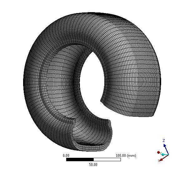
You could create an undeformed tyre (tire for my friends in the USA) by using a very few points in that file. Take the one point at the center and the few points at X=0 and Z>0. In the first image in my post above, you can see that there are three elements through the thickness, or four rows of nodes. You need to delete all the interior nodes, leaving just the outer and inner surface nodes. Unfortunately, there is no easy way to put those nodes in the correct "connect-the-dots" order to draw a curve through them, but you could import the points, then create the curve by manually connecting the points. That will give you a closed curve of the tyre cross-section. If the points look symmetric, you could just draw half then use a mirror function. That closed curve can be rotated around the center point to form a solid model of an undeformed tyre.
Regards,
Peter -
November 5, 2018 at 1:43 pm
mariannebassil
SubscriberDear Peter, i already have the undeformed tyre . I have drawn it by importing points than joining them by a line than revolve. These points were the first part of my question above but now i want the deformed tyre so i got it from an ABAQUS file in an .inp file but the Design modeler doesn't read the .inp so i opened it as .txt and extract the node points... I don't know what to do in order to have the deformed desired surface of the tyre
-
November 5, 2018 at 1:47 pm
mariannebassil
Subscriberthe .inp file contained lots of tables , what i sent to you was just the nodes points ( there are also elements and many but i dont know what to use in order to have the surface) . I have also a question! how did u do to obtain the whole tyre? because when i open the file in Design modeler as points i just obtain the dark part of the tyre( the deformed part) no all the tyre
-
November 5, 2018 at 6:09 pm
peteroznewman
SubscriberDear Marianne,
Since you have an ABAQUS inp file, insert an External Model item into Workbench and read the entire .inp file to get a complete mesh and a Geometry representation of the mesh. Here are some ANSYS Help screen images in the External Model
Your text file has 72,000 rows of data and I think DesignModeler won't read more than 2,000 points at a time. I made those plots outside of ANSYS using JMP.
Kind Regards,
Peter -
November 6, 2018 at 6:44 am
mariannebassil
SubscriberSo if i can't import more than 2000 than there is no need to pass through the external model than Design modeler? i have to think about something else? u mean ? And can you export the JMP as step format so i can read it directly into Design modeler ?
-
November 6, 2018 at 7:25 am
mariannebassil
SubscriberANd i don't find the external model option in my workbench options although i have done an installation for the mechanical products
-
November 6, 2018 at 11:41 am
peteroznewman
SubscriberDid you expand the Component Systems category and look there for External Data?
JMP is just plotting all the points, it doesn't assemble a solid model around them. Some CAD systems can take a cloud of points and do that, but you don't need to because you have the entire ABAQUS .inp file that connects all the points with elements, and External Data will provide a solid model for you.
I am curious to try the External Data myself. Zip the ABAQUS .inp file into a zip file, and if the zip file size is < 120 MB, please attach it to your reply.
-
November 6, 2018 at 12:19 pm
mariannebassil
Subscriberyes i found the external Data but i dont find the external model neither the external model ! anw i will zip the inp file and send it to you! if not can you send me your mail so i will send it to you for capacity problem
-
November 7, 2018 at 9:08 pm
peteroznewman
SubscriberHello Marianne,
What version of ANSYS are you using?
I read your inp file into an External Model and linked a Mechanical Model that has a solid and a mesh.
It looks like you are missing the deformed section in the inp file.
Regards,
Peter
See the related question in this discussion.
ANSYS 19.2 archive attached.
-
November 9, 2018 at 7:29 am
mariannebassil
SubscriberHello I am using ANSYS 19.2 but i don't have the ANSYS Mechanical license to open the file. We are going to order a test license! Thank you anyway for your help at least i can see the geometry above but I don't know what is the problem I gave you the same inp file as above how comes that with the JMP software it read all the points!
-
November 9, 2018 at 8:34 am
mariannebassil
SubscriberI tried to get the odb file rather than exporting it in an inp file ( maybe this was the problem that prevented to show the deformed part) . Can you try reading the attached file in the external model ?
-
November 9, 2018 at 5:45 pm
peteroznewman
SubscriberThe External Model does not read ABAQUS .odb files.
-
November 13, 2018 at 2:55 pm
mariannebassil
Subscriberhey Peter! I contacted ANSYS mechanical. He found that the problem was with the type of the elements in the inp file ( he replaced CCL 12 by C3D8H and removed the 4 last columns of these elements (i attached the corrected inp file). He sent us a screenshot of the geometry that looks good ( we can see the complete tyre however i don't have the mechanical license in order to check in detail if this is the needed geormetry). So please can you try now with the new inp file (attached) and send me the generated geometry ( design modeler format or any format that i can import through design modeler in order to open it and see it )
Thank you in advance
-
November 13, 2018 at 5:29 pm
-
February 10, 2019 at 8:11 pm
Akshaydey
SubscriberHi Peter,
I have tried to import a 3D curve with the supported format ( as also described by you above),but ANSYS DM shows an error message.
I've tried to create a closed curve, thus have put '0' in column B at the end and the rest coordinates blank.
The below is the text file.
Can you help pointing the problem?
Thanks.
Â
-
February 11, 2019 at 1:42 am
-
March 2, 2019 at 6:36 am
Akshaydey
SubscriberThank you, Peter
It was my mistake.
-
March 15, 2019 at 2:56 pm
Aditya663
SubscriberHi, im trying to design my BAJA rollcage in the design modeler for 1-D meshing and analysis purpose. I imported the points of my rear loop of the roll cage, using the method as said above. The problem with the 3-D curve is that my whole loop is in the form of continuous curve. I wanted to give fillets of 4" at the places where there are bends but, due to this problem, im not able to continue. Is there a way in which only points are imported, instead of a continuous curve in the design modeler itself?
Thank You.
Â
-
May 14, 2019 at 6:49 am
mariannebassil
Subscriber@peteroznewman can you please send me your mail ? i need to contact you
Â
-
May 14, 2019 at 7:52 pm
peteroznewman
SubscriberSorry, Marianne, I do all my communication on the site and don't share my email.
-
May 3, 2023 at 5:16 am
Clifford Omonini
Subscriberplease i need assistance
Â
-
-
May 2, 2023 at 9:57 am
Clifford Omonini
SubscriberPlease i need assistance.
I actually have two curves i am trying to plot and i have the excel data. I tried the methods here but couldnt get the curves.Â
Â
-
- The topic ‘drawing a geometry by importing a table of points’ is closed to new replies.
-
3145
-
1007
-
935
-
858
-
792
© 2025 Copyright ANSYS, Inc. All rights reserved.