TAGGED: #fluent-#ansys, boundary-conditions, fluent, interface, mesh
-
-
September 12, 2023 at 10:51 pmKyle BeveridgeSubscriber
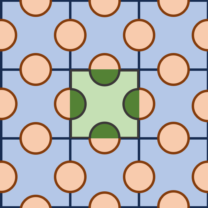
The goal of my recent simulations has been to establish a process for simulating components such that both solid and fluid regions are modeled in a periodic behavior within the same unit cells. Â I have included a figure below displaying a cross-section of a problem similar to the one I'm working with. Â In the cross-section, the orange and dark green are the solid parts, and the blue and light green are air, with the green unit cell signifying the one I am trying to simulate.ÂÂI believe my main difficulty at the moment is that I cannot create more than 1 set of conformal zones in the meshing workflow and have not been able to find a process to mesh conformal zones in outline view in Fluent Meshing, but there may be more to it.Â
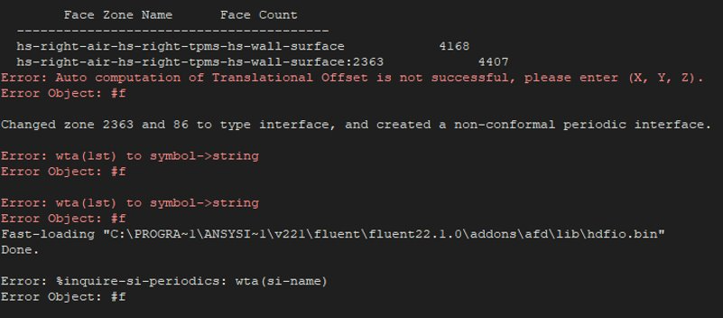
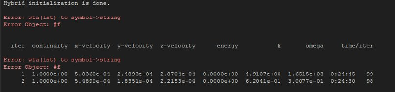
Previously, I have attempted to use non-conformal zones, but have run into odd errors, particularly when creating the periodic boundary condition itself. Â Once the zones are set to periodic, it throws odd errors then the solver will automatically name the periodic BC "#f" then display the continued errors below and will behave in a very reduced functionality. Â This reduced functionality as of now has meant no writing case/data, an error when beginning to solve then proceeding as normal, no post-processing tools displaying in outline view, and so on.ÂÂDoes anyone by any chance know what I may be missing and how to fix it?
-
September 13, 2023 at 9:17 amRobForum Moderator
You've got a couple of problems with the above. Check the periodic section in the Heat Transfer chapter of the User's Guide to explain the solid limitations. You then have one pair of periodic boundaries to use: typically the other pair are symmetry.Â
-
September 13, 2023 at 12:38 pmKyle BeveridgeSubscriber
Thank you for a quick response, I have a couple of questions regarding both sides of this.
Â
"Check the periodic section in the Heat Transfer chapter of the User's Guide to explain the solid limitations."
Thank you, I plan on using coupled wall interfaces for these cases, but have had issues getting it set up because of the errors including "#f". This seems to work in 2023 R1, but due to the resources available, I can not use it as a long term solution as of now. Do you happen to know what may cause that error?
Â
"You then have one pair of periodic boundaries to use: typically the other pair are symmetry."
To confirm, this means we are unable to model flows that are periodic in 2 directions as of now unless we include the entirety of one of the directions? Symmetry would not work with the geometry that I'm using on the case I'm trying to run.
-
September 13, 2023 at 1:13 pmRobForum Moderator
Solids that bridge the periodic are a problem - hence the comment to check the thermal section as periodics are covered in two sections of the User's Guide.Â
In the periodic section there's a flow direction assignment. You can get creative with that, but without knowing what you're actually looking at it's difficult to see if that can be done here.Â
-
September 26, 2023 at 4:30 pmPrashanthAnsys Employee
Hello Kyle,
Below are my additional comments to your two questions:
-- 2 pairs of periodics: I assume yours is a 3D model. It is possible to have two periodic pairs here. Try to get a matching conformal mesh along the translational directions of the periodics. And help Fluent by providing the exact offset distance. For 2D model, it is one symmetry and one periodic pair.Â
-- solid zones across periodics with energy: This is not supported as documented in the User docs:Â 14.4.1.2. Constraints for Periodic Heat Transfer Predictions.The red colored warnings can be due to this reason.
Let me know if you need more help with this.
-
October 4, 2023 at 6:08 pmKyle BeveridgeSubscriber
Yes, it is a 3D model. How do you get conformal mesh in 2 directions? When I have attempted, I can only get 1 pair properly, then tried copying the 2nd pair, which of course had to be intersect/joined which then left it non-conformal, so I am at a bit of a crossroads on that front.
As far as solid zones go, could I model them a fluid with infinite (very high) viscosity instead? I am mainly looking for conduction from one end to the other because the solid region acts as a fin in a way. I am open to any suggestions.
Â
Thank you
Â
-
October 5, 2023 at 8:19 amRobForum Moderator
The problem is you're creating a second zone that isn't flowing and also bridges the periodic. The approach works by passing flow data from one end to the other, that's "easy". Energy works by having a fixed temperature on the upstream end, and then in/de-creasing the temperature along the section to give a dT.Â
There is a mesh trick, but I need to check it's "common knowledge" as we used to do that with tfilter and some creative thinking.Â
-
October 5, 2023 at 8:39 amRobForum Moderator
Try searching "mirror" in Search Knowledge on here. Strictly, we're not linking faces to be identical but can mirror the domain so the faces are identical.Â
-
- The topic ‘Fluent 2022 R1 Periodic Interface’ is closed to new replies.
- How do I get my hands on Ansys Rocky DEM
- Non-Intersected faces found for matching interface periodic-walls
- Unburnt Hydrocarbons contour in ANSYS FORTE for sector mesh
- Help: About the expression of turbulent viscosity in Realizable k-e model
- Script Error
- Mass Conservation Issue in Methane Pyrolysis Shock Tube Simulation
- Facing trouble regarding setting up boundary conditions for SOEC Modeling
- convergence issue for transonic flow
- Running ANSYS Fluent on a HPC Cluster
- Point exception in erosion calculation
-
1897
-
807
-
599
-
591
-
366
© 2025 Copyright ANSYS, Inc. All rights reserved.