-
-
September 8, 2023 at 1:34 am
Yun
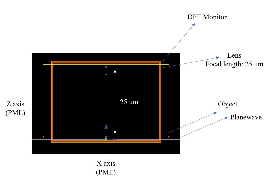
SubscriberWhat I want is to compare the shape of the image reduced and enlarged by magnification with the reference. The explanation below is related to my setup, but I wonder if there is a better way than this, and I want to know if there is a problem with my setup.Description: I designed a lens with a focal length of 25 um and designed it as shown in the figure to evaluate the performance of the imaging optical system. The distance between the object and the lens is separated by the focal length f, and we want to view a 2D electric field image in a farfieldexact3d script at a distance of f+f*M (magnification) after the lens (e.g., X,Y image plot at the Z-axis 11*f position)Should I write another farfield script?Should the location of the monitor and source be modified?It's currently set to PML, can I use symmetric?Any help would be appreciated.and this is my script, when M is 400:mname = "DFTMonitor";
num = 100;
x = linspace(-1e-3, 1e-3, num);
y = linspace(-1e-3, 1e-3, num);
z = 10e-3;
E = farfieldexact3d(mname, x, y, z, {"field":"E"});
Ex = pinch(E, 4, 1);
Ey = pinch(E, 4, 2);
Ez = pinch(E, 4, 3);
E2 = abs(Ex)^2 + abs(Ey)^2 + abs(Ez)^2;
image(x*1e3, y*1e3, E2, "x (mm)", "y (mm)", "abs(E)^2");
-
September 8, 2023 at 6:41 pm
Guilin Sun
Ansys EmployeeYou do not need to simulate so long in z axis, since it is in the uniform material. What you should do is, place the monitor close to the lens which significantly reduces the simulation volume and simulation time. Then you do one farfieldexact projection along z, to find where the image plane is. Usually we define the focal plane at the max axial intensity. Once you get this location, use it to do a second farfieldexact calculation for this plane so you will know the image spot.
Please refer to the metalens example https://optics.ansys.com/hc/en-us/articles/360042097313-Small-Scale-Metalens-Field-Propagation
-
September 9, 2023 at 2:42 am
Yun
SubscriberThank you for your reply.
My lens structure and DFT monitor are already quite close, as shown in the picture in my initial questionnaire.What I'm curious about is the idea that if you put the lens and the object closer than the focal length from the point of view of imaging the object, the vinetting will occur and the imaging will not work properly.
In the figure above, the focal length of the lens is 25 um, and the distance between the object and the lens where the planwave was incident is set to 25um.
Of course, for a 3D FDTD with a z-axis of 25 um, meshing is incredibly slow and requires a lot of resources. I don't want this.
I just wanted to know if there was another way and if I could stick it close as you said.In general, when I thought about the imaging optical system configuration, I thought that the gap between the object and the lens should be separated by the focal length of the lens.
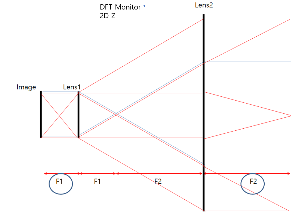
I circled F1 and F2 and you might think that it's okay to ignore the distance because it's the same plane wave from the Ray base
From an imaging perspective, you must keep that F1,F2 distance, but doesn't this mean that if F1,F2 changes, it will lead to Vignetting when imaging?
But the simulation results are strange.
I constructed the object as 5*5 rectanglery.
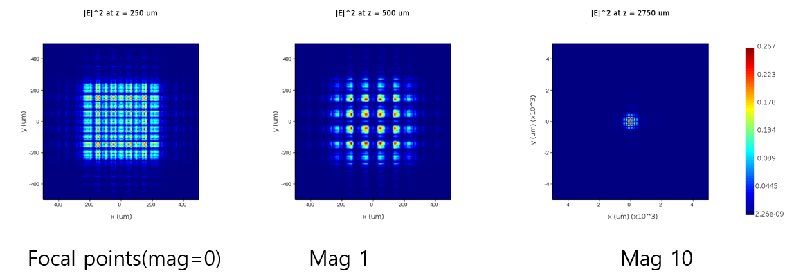
After the planewave passed through the object, the image at the design focal length position of the lens was checked by farfieldexact3d.Here are two types of pictures. the lens designed 250 um focal length
1. When the object and the lens are not separated by the focal length of the lens.
2. When the object and the lens are separated by the focal length of the lens.
And the important thing is that if the focal length of the lens is 250um and mag is 10, the z-axis of the x and y image that I have to look at should be 11*f (250um) and the X and Y range of the image should be 10 times larger to see the entire object.
However, both of the above types of results have not been properly represented by a 10x rate image. Why? I'm curious.
-
September 11, 2023 at 4:46 pm
Guilin Sun
Ansys EmployeeI do not believe that you can still use geometric optics concept to define the imaging process when at the wavelenght scale. In such case how do you define the focal plane? The axial max intensity may not be the geometric focal point.
I would strongly suggest you to do two simulations 4 steps:
step1: object +plane wave
step 2: propagate the fields to in front of the lens
step 3: simulate the lens with import source
step 4: propagate the fields to the image plane as suggested previously
When one more lens is invloved, do the same thing.
If geometric optics works you do not need to simulate it with FDTD.
-
September 12, 2023 at 1:40 am
Yun
SubscriberThank you for your reply.
First of all, my lens is a zone plate lens.
It has a special structure, so I can't do it even if I want to do it with Zemax. (That's a lot faster ^^,,)
By the way, I have checked the position of the lens focus through 2D FDTD. So we know the exact focal length of the lens, 250 um.According to my understanding, the simulation should be carried out twice in total,
The first simulation is to simulate a planwave propagating through an object,
In the second simulation, I think we should take the ZBF file from the first simulation and use the import source function to enter the import source into len for simulation.
Is this right?
If this is correct, I don't think it matters if you keep planwave and object close to each other in the first simulation setting, but how far should you keep object and DFT Monitor apart?Also, should I set the DFT Monitor to extract ZBF to 3D structure and proceed with the simulation?
In the second simulation, how much should the import source be separated from the len?
I'd appreciate it if you could answer.
-
-
September 12, 2023 at 1:31 am
Yun
SubscriberThank you for your reply.
First of all, my lens is a zone plate lens.
It has a special structure, so I can’t do it even if I want to do it with Zemax. (That’s a lot faster ^^,,)
By the way, I have checked the position of the lens focus through 2D FDTD. So we know the exact focal length of the lens, 250 um.According to my understanding, the simulation should be carried out twice in total,
The first simulation is to simulate a planwave propagating through an object,
In the second simulation, I think we should take the ZBF file from the first simulation and use the import source function to enter the import source into len for simulation.
Is this right?
If this is correct, I don’t think it matters if you keep planwave and object close to each other in the first simulation setting, but how far should you keep object and DFT Monitor apart?Also, should I set the DFT Monitor to extract ZBF to 3D structure and proceed with the simulation?
In the second simulation, how much should the import source be separated from the len?
I’d appreciate it if you could answer.
-
- The topic ‘3D FDTD, Farfield, Imaging optics’ is closed to new replies.


-
4592
-
1494
-
1386
-
1209
-
1021

© 2025 Copyright ANSYS, Inc. All rights reserved.


