-
-
September 7, 2023 at 6:56 pm
-
September 8, 2023 at 1:58 pm
Praneeth
Ansys EmployeeHi Imtiaz,
Thank you for reaching out to the Ansys learning forum.
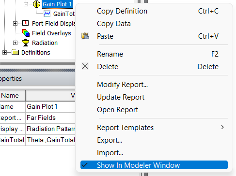
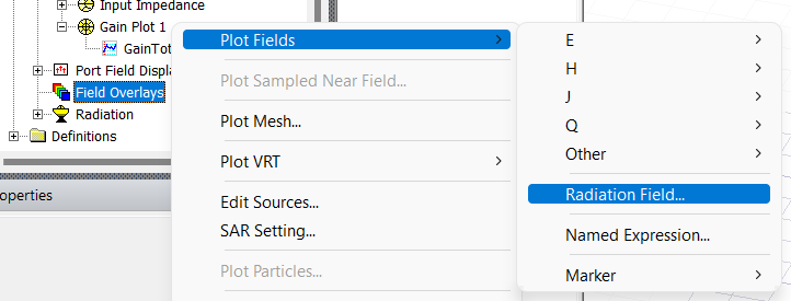
Please note that the 2D radiation pattern is cut plane view of the 3D radiation pattern by fixing the value of phi or theta. In your case, theta is varied from -180 to 180 for a fixed phi value. For better understanding, you can overlay these radiation patterns (for a single phi or theta value) in the 3D modeler window on the antenna geometry. See the below image for the steps.
You can also change the scale and transparency of these plots using the following steps.
Kindly go through this free video course on the analysis of the patch antenna for detailed information - Microstrip Patch Antenna Array - ANSYS Innovation Courses.
Please note that Ansys personnel cannot guide you on your other question as it is on design guidance, so check with your seniors or mentors or any other experts in the forum who can guide you.
Best regards,
Praneeth.
-
- The topic ‘Is there anyone who could help me in understanding this 2D radiation pattern?’ is closed to new replies.


-
4959
-
1639
-
1386
-
1242
-
1021

© 2026 Copyright ANSYS, Inc. All rights reserved.


