Hello,
I have modeled a timber beam in LS-DYNA. In this regard, I used *MAT_WOOD which is a transversely isotropic material. I intend to define a proper material coordinate system so that the model can realistically behave. I have read LS-DYNA Manual regarding *MAT_WOOD, ELEMENT_SOLID_ORTHO, and other relevant sections. I will describe the steps I went through to define the proper material coordinate system for the model.
I would appreciate it if you could give me some advice.
Thanks in advance.
Regards,
Mehdi
Step 0: FEM Model
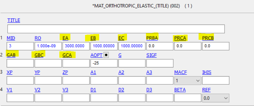
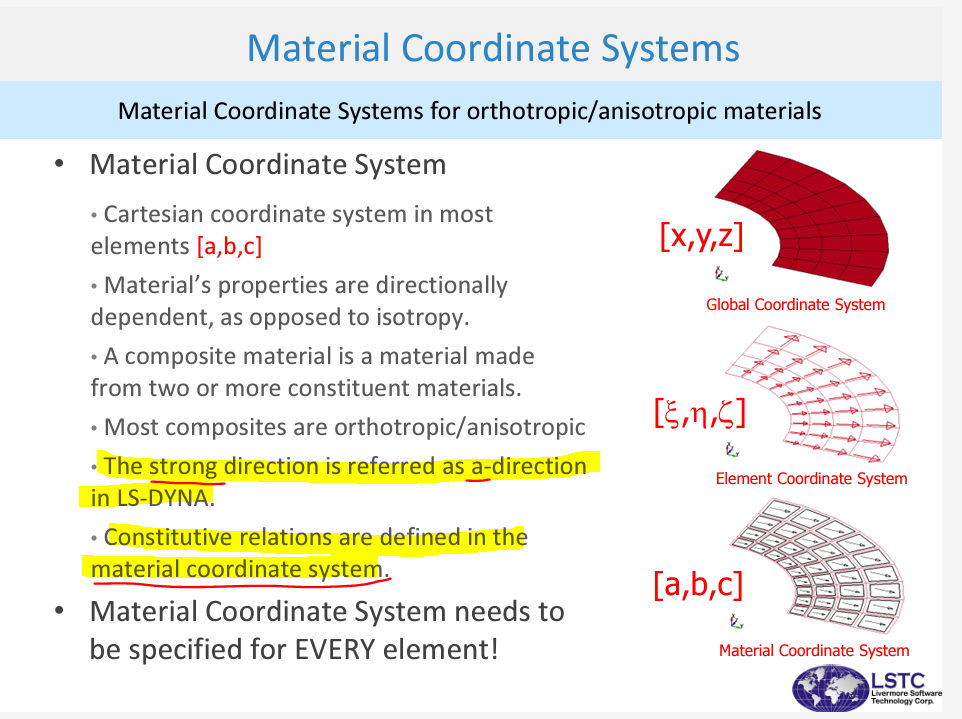
Wood is an orthotropic material because it possesses different properties in three directions―longitudinal, tangential, and radial. A common assumption is that wood is transversely isotropic which means the properties in the tangential and radial directions are modeled the same (*MAT_WOOD). The parallel direction refers to the longitudinal direction (L) and the perpendicular direction refers to the radial or tangential direction (T).
For my FE Model, longitudinal direction (L) is along the global Z axis and transverse directions (T) are along the global X and Y axes. Therefore, longitudinal stiffness and strength properties (EL, XT, XC, …) should be assigned to the global Z axis of the specimen and perpendicular stiffness and strength properties (ET, YT, YC, …) should be assigned to the global X and Y axes of the specimen (see the picture 1).
Picture 1: The timber beam and global coordinate system (x, y, and Z)

Step 1: Material Directions for the Wood Material Model (AOPT=2.0)
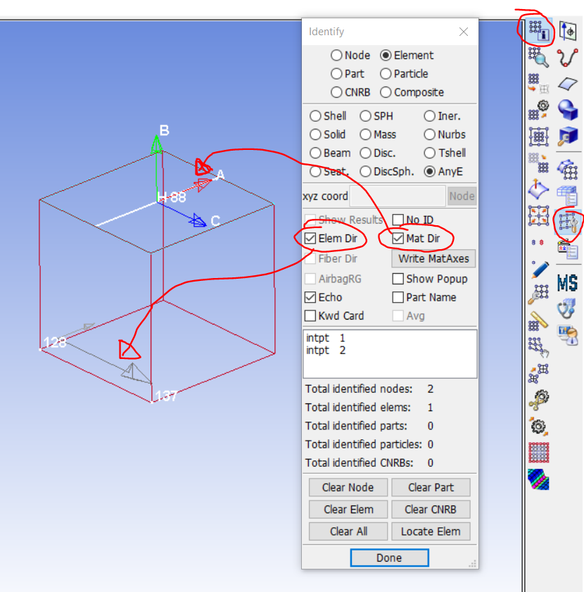
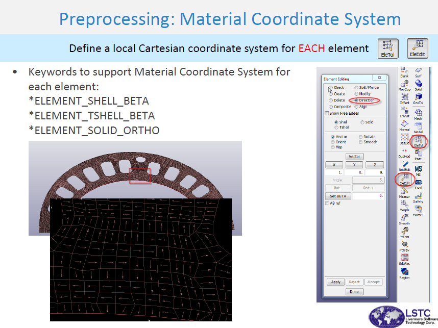
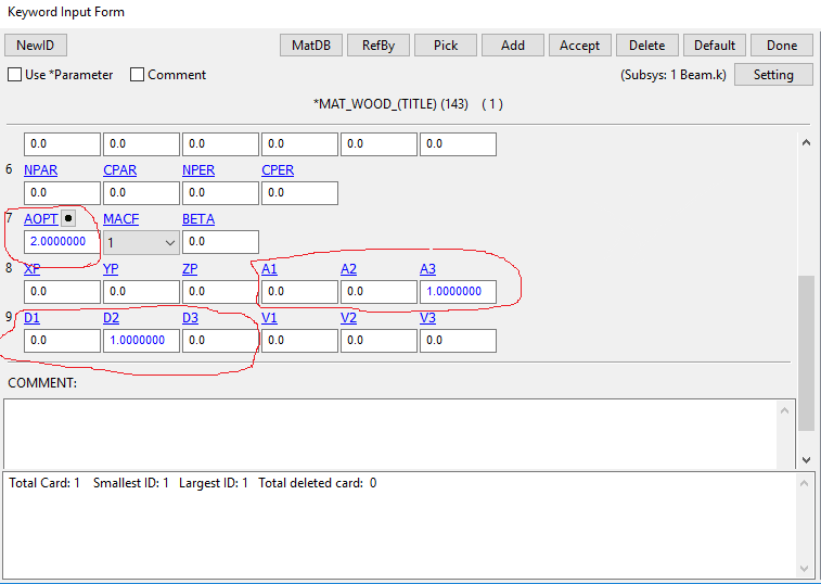
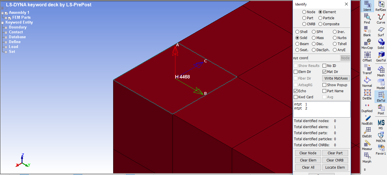
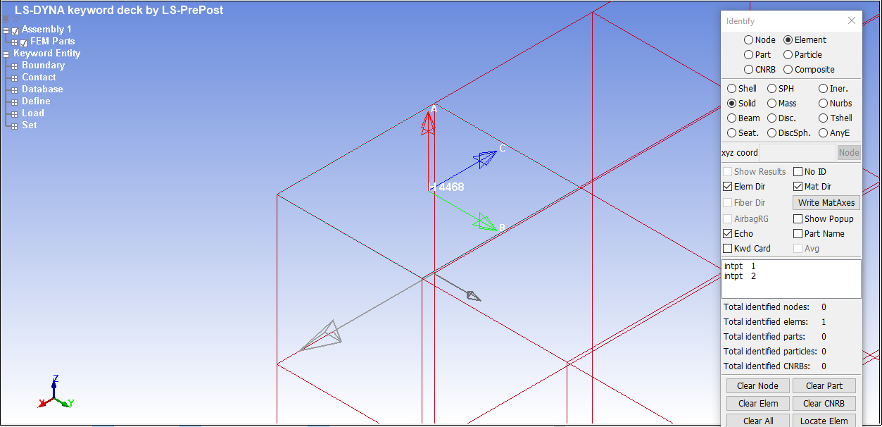
I used the AOPT material axes option (AOPT = 2) and defined vectors a and d. The vector a is the parallel-to-the-grain direction (L) and d is one of the perpendicular-to-the-grain directions (T). Then, a x d = c and c x a = b, where a, b, and c are the principal material axes. Please see the following pictures. Please note that we have solid elements so far (see picture 5).
Picture 2: AOPT material axes option (AOPT = 2)
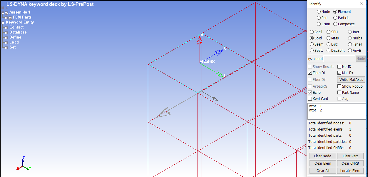
Picture 3: Display the material coordinate system for solid elements (Mat Dir: shows the material direction orthotropy defined by the AOPT)
Picture 4: Display the local element coordinate system
Picture 5: Solid elements for timber beam
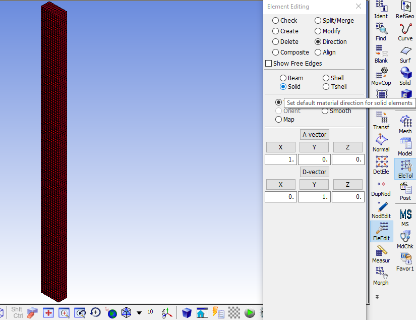
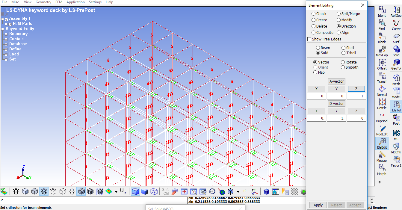
Step 2: Setting the direction of orthotropy axis 1 of the material
On the following page of your website, it is mentioned that “In Element Tools > Element Editing, the Direction option sets the direction of orthotropy axis 1 of the material.”
/forum/forums/topic/element-direction-in-ls-prepost/
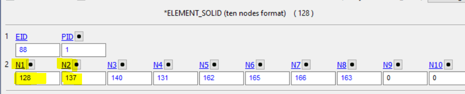
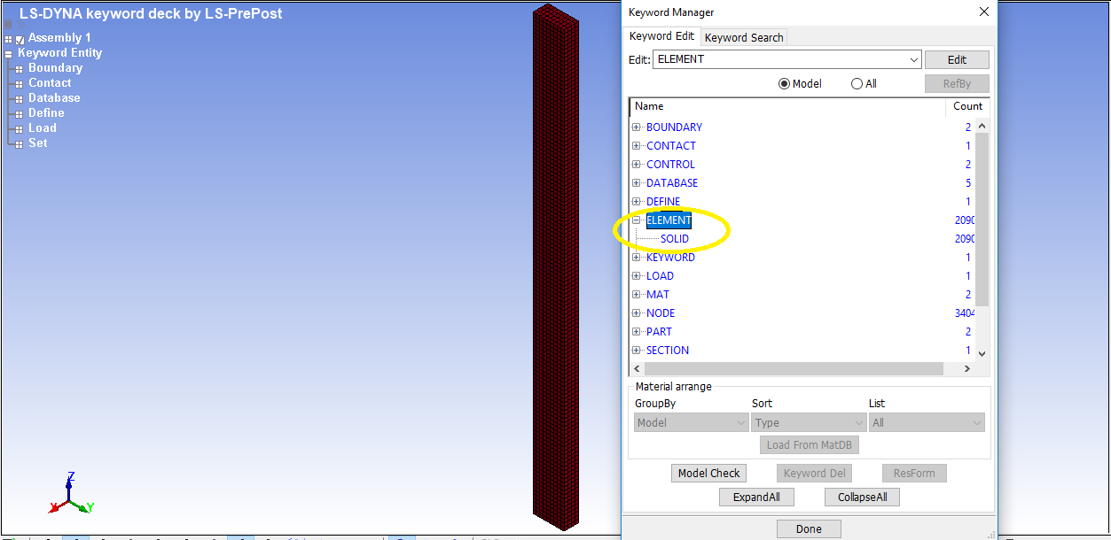
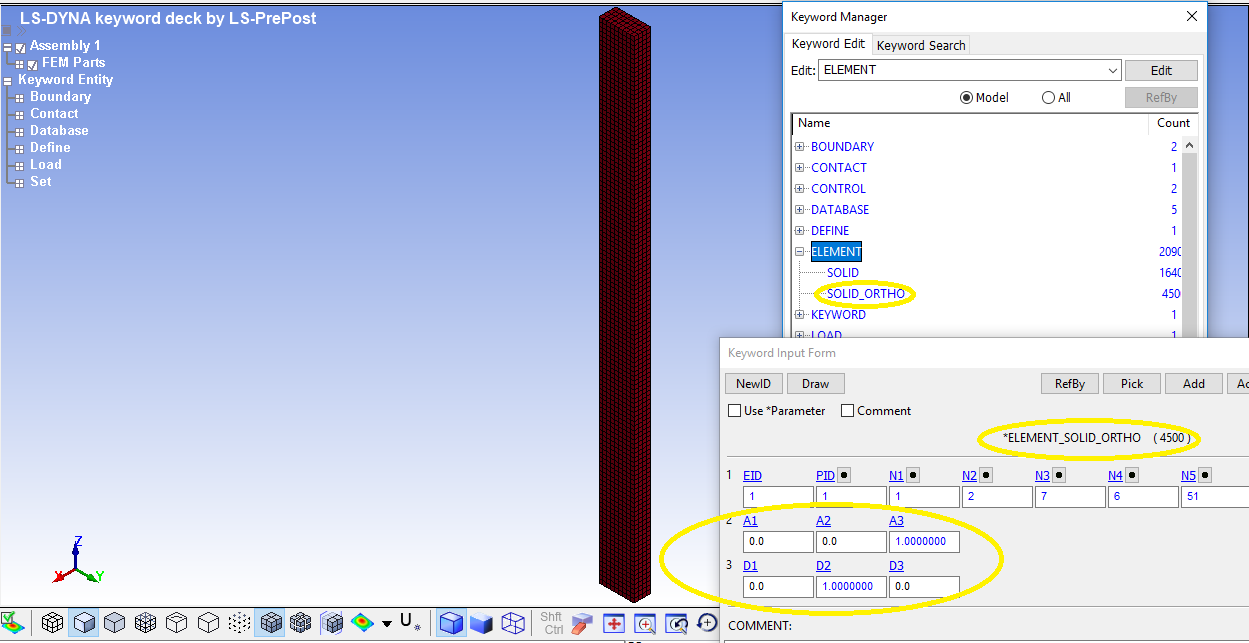
As you can see in picture 6, it seems that this direction is wrong and should be along the global Z axis. Therefore, I changed the direction and set it along the global Z axis (Picture 7). After that, the elements for the beam changed to ELEMENT_SOLID_ORTHO as you can see in picture 8. It is also noteworthy to mention that the element direction does not change according to picture 9.
Picture 6: The direction of orthotropy axis 1 of the material
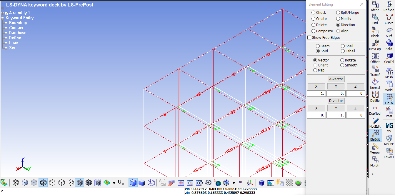
Picture 7: Setting the direction of orthotropy axis 1 of the material along Z axis
Picture 8: Solid_Ortho elements for timber beam
Picture 9: Display the local element coordinate system