-
-
September 9, 2018 at 2:05 pm
Rana Nasser
SubscriberHi Everyone,
I need to do the simulation shown in the picture below, but I couldn't assign the mass to the spring's end or start. I'm using the method in the attached video to add the spring to the structure, so is there any edit or to this method to allow assigning a point mass to the spring's end or start point? or an APDL command to do this?
https://www.youtube.com/watch?v=JXPC1cNHQrg
-
September 9, 2018 at 3:00 pm
peteroznewman
SubscriberHi Rana,
I recommend you follow the video and draw a block, make it Rigid, and use a Remote Displacement on the front face to turn it into a 1 DOF motion along the x-axis. Add a spring (K/2) to ground on each side of the block. Or just use one spring (K), since it is an idealized 1 DOF system anyway.
Adjust the density of the material for the block until you get the mass you want. Or you can add a point mass to the back face of the block and assign the difference the point mass a value of the difference between the desired mass and the current mass of the block, assuming the current mass is less than the desired mass.
Regards,
Peter
-
September 9, 2018 at 3:12 pm
Rana Nasser
SubscriberHi Peter,Â
In my simulation the mass "M1" refers to the convective water mass in a water container not a real block
Â
-
September 9, 2018 at 3:18 pm
peteroznewman
SubscriberHi Rana,
Okay, but if you want to study the dynamics of a mass and spring system, and you are idealizing the mass to a point mass and are idealizing the springs to linear elastic springs, then the dynamic response is the textbook case of a Mass-Spring system. I can write the equation of motion for that, or I can build a model to simulate the response and let ANSYS numerically calculate the response.
You might want to compare the textbook Mass-Spring system to the response of a more complex system to draw analogies, or to make a 1 DOF representation of a complex system. In that case, it doesn't matter if you replace the convective mass of water with a rigid solid body, it is an idealization of the system to a 1 DOF system.
Regards,
Peter
-
September 9, 2018 at 3:42 pm
Rana Nasser
SubscriberI'm studying the dynamic response of a water structure elements and I need to simulate the water contained in the structure. this method is a simplified to do this simulation which used in a published paper and the author used this procedure using ansys apdl 15.0 by employing mass21 and combine14 elements, and I'm trying to use this method in my regulator( water structure) model.Â
the simplification procedure of the water response to a dynamic load is as shown in the pictures below
Â
-
September 9, 2018 at 7:32 pm
peteroznewman
SubscriberUsing Mechanical without any APDL commands, you need a body to add a point mass and springs to.
I don't know how to write the APDL command to create the node and assign the mass element, but I know it is possible.
Regards,
Peter
-
October 24, 2018 at 2:43 pm
Rana Nasser
SubscriberHi,
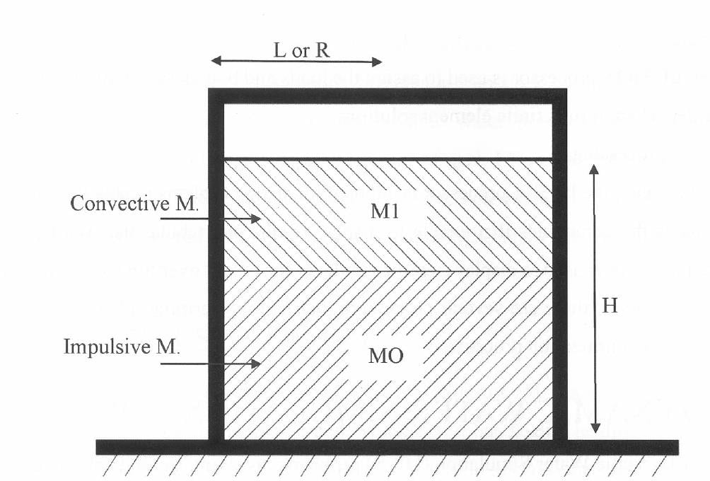
To apply the above water modeling approach in ansys WB (mechanical) I ave used remote attached point masses to model (M0) and a 1m3 solid box ( I had added it to the model in design modeler) connected to the structure with 2 longitudinal springs as shown in the images below.
when I tried to solve the model this warning "Two or more remote boundary conditions are sharing a common face, edge, or vertex.  This behavior can cause solver overconstraint and is not recommended, please check results carefully. You may select the offending object and/or geometry via RMB on this warning in the Messages window." was appear then the solution stopped with this error "At least one contact pair or remote load has no elements in it. This may be due to mesh based defeaturing of the geometry. You may select the offending object via RMB on this warning in the Messages window.".Â
To handdel the error I turned the mesh defeaturing option to "no" and tried to solve again, but I get the same warning and the same error. Could anyone give a hand please?!!
 Note: the springs and the point masses are attached to the structure using x, y, z location with the remote attachment method and their locations may not match nodes locations.
Â
-
October 24, 2018 at 3:35 pm
peteroznewman
SubscriberHi Rana,
I see you have a rigid body, 1 m^3, to represent the water and you have springs from that to each wall, but I don't see why you would have a point mass on the wall. The wall has its own mass. Instead of adding a point mass, why not just increase the density of the wall?
Also, is each spring scoped to the adjacent wall? I see one highlighted face in the last image. I hope that is for the front left-side spring and no other.
If you want to attach an archive, I will take a closer look.
Regards,
Peter -
October 24, 2018 at 4:01 pm
Rana Nasser
SubscriberHi peter,
To simulate the water using "Housner's method" as shown in the next image I have to divide the water into 2 masses M0 and M1. M0 will be attached directly to the walls at a specific height and M1 will be attached to the wall with the 2 springs at another specific height, so I can't add M0 masses to the walls masses!
Secondly, yes the highlighted face is for the front left- side spring, but for the springs that locates after the gates each wall face is connected to 3 springs and each spring is remotely attached to the wall at a specific location defined by x, y, and z and there is no any intersections between all the springsas shown in image 2
image 2
-
October 29, 2018 at 8:35 am
Rana Nasser
SubscriberI tried also to attach the point masses to a named selection not to the face, but I got the same warning and error. Is there any inspirations?!
-
February 2, 2019 at 4:37 pm
jehanzeb
Subscriberi am also trying to simulate the above model by line element and point mass but continuous solver error need your help how you done this thanks Â
-
- The topic ‘how to assign a point mass to a spring’ is closed to new replies.
-
2577
-
933
-
792
-
599
-
591
© 2025 Copyright ANSYS, Inc. All rights reserved.