-
-
August 16, 2023 at 6:29 pm
javat33489
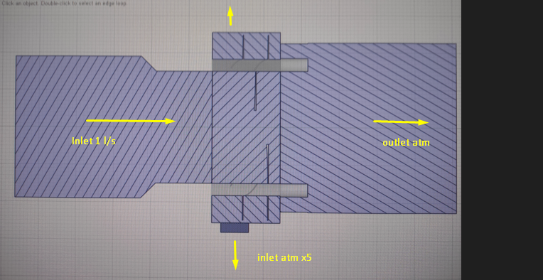
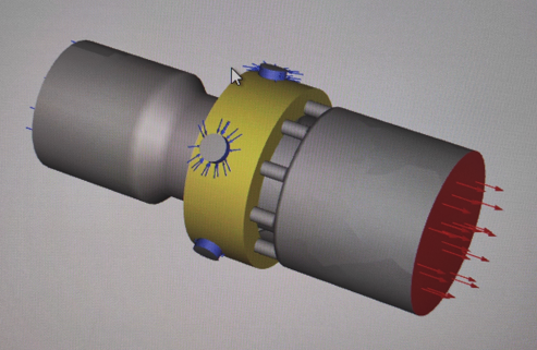
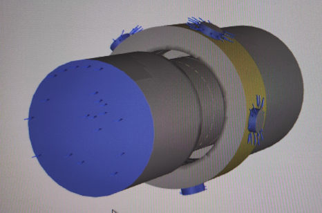
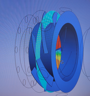
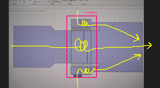
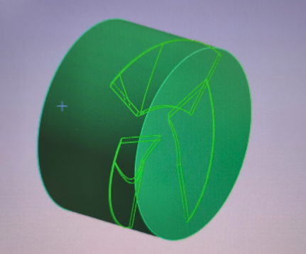
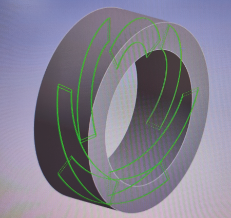
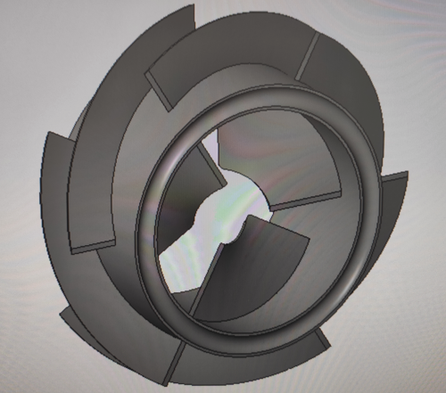
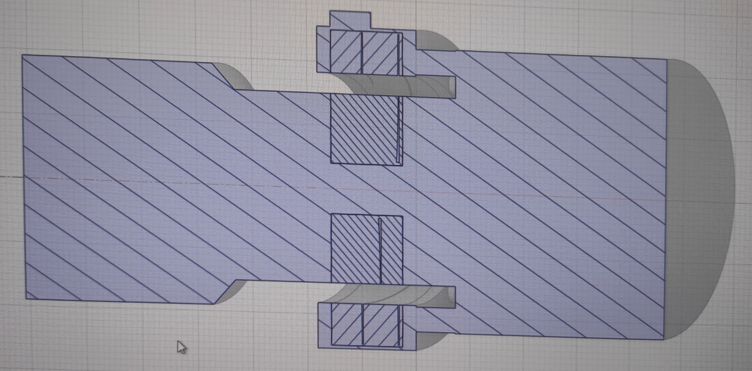
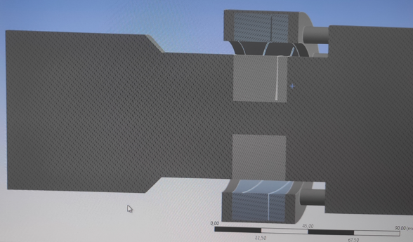
SubscriberHi all. I am calculating a test model. I made such a model where there is a centrifugal pump wheel in the pipe. The fluid drives it with a flow through the center, impellers are in the center. There are also impellers outside the wheel, they are directed in the other direction. Thus, when the water accelerates the wheel, it begins to drive water from the upper circuit.
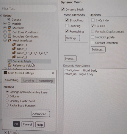
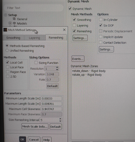
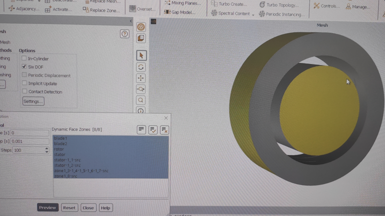
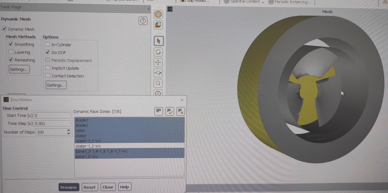
I'm using a dynamic mesh for a spinning wheel. But it doesn't spin!
So I will show the basic settings and show the result.
I am using the SST model. The SIMPLE calculation method is all second order. The pumped medium is water. At the inlet 1 l / s, at the outlet atmospheric pressure, as well as the inlet to the second circuit is also atmospheric pressure.
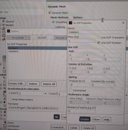
Mesh settings:
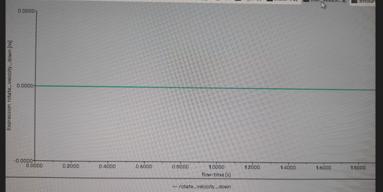
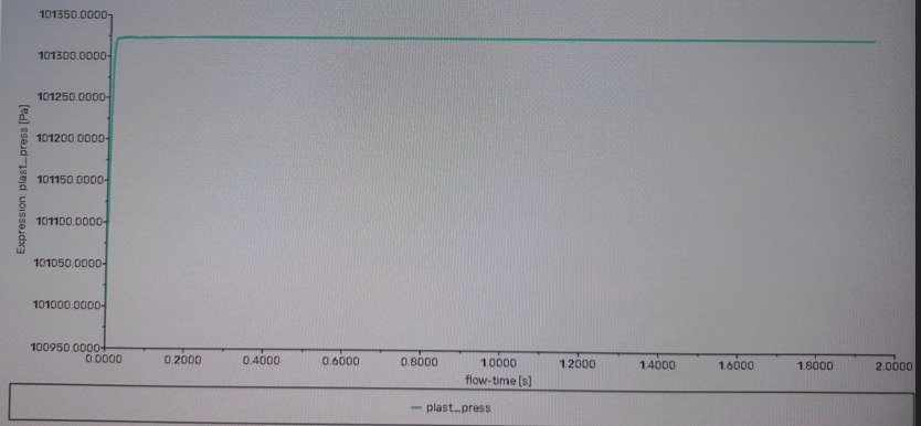
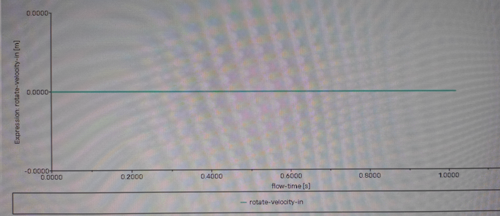
I decided to track the rotation of this area using the expression:
Rotation does not occur.
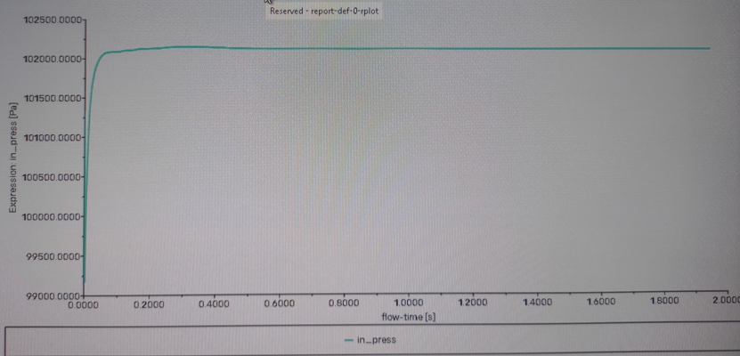
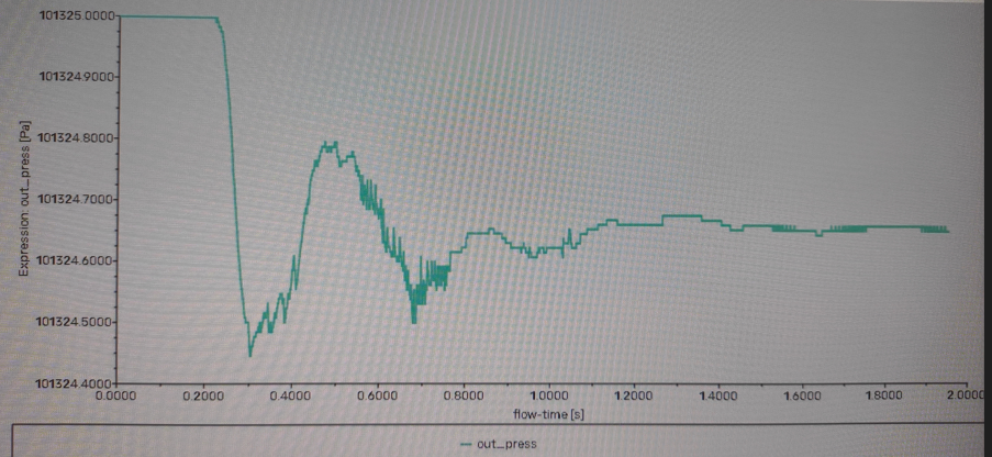
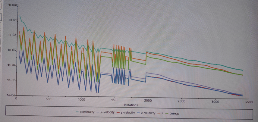
The results show that the fluid flow has returned to normal:
inlet pressure
outlet pressure
pressure 2 (5x)
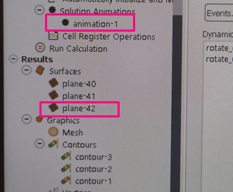
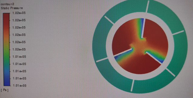
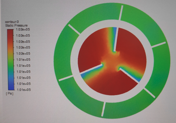
I also tracked the rotation using animation by animating a section with pressure:
There is no rotation.
Please. Help start spinning the wheel?
-
August 19, 2023 at 10:53 am
javat33489
SubscriberHello. I tested the dynamic grid by adding a rotor and a stator. I made 5 options but it didn't work for me. I'm surprised why it doesn't work. Somewhere an error. Help me please.
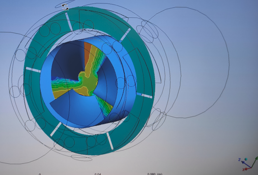
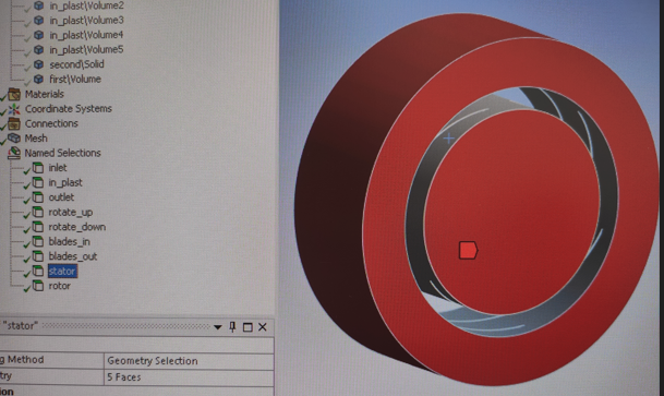
I made a selection of faces for the shoulder blades.
And this is how the wheel originally looked, before extracting the volume around it:
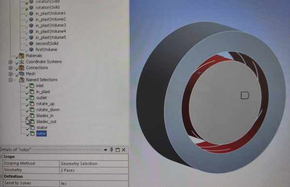
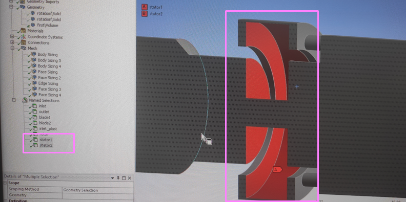
I also made the rotor and stator faces:
Next, I made 5 variants of tests.
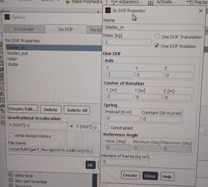
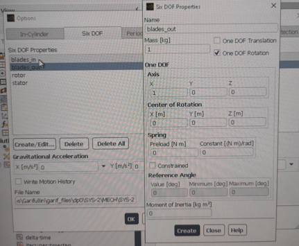
1.Blades rotating along the X axis. For the inner and outer blades, the same settings:
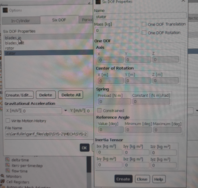
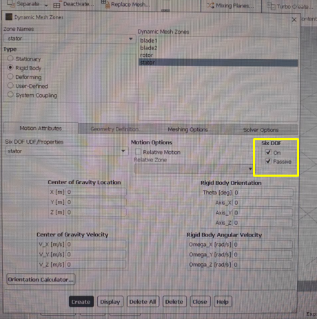
Stator and rotor with the same settings without rotation, and the passive checkbox is also enabled:
The area does not rotate, you can see it in my rotation sensors and in the animation.
2.Blades rotating along the X axis. Settings as in 1.
Stator and rotor with the same settings without rotation (settings as in 1). The stator is passive. Rotor is on (not passive).
The area also does not rotate.
3.Blades rotating along the X axis. Settings as in 1.
The stator is passive. With settings without rotation.
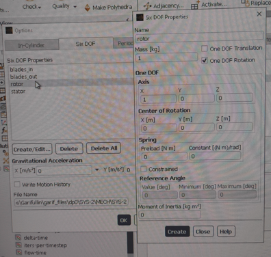
Rotor passive with rotation settings:
The area also does not rotate.
4.Blades rotating along the X axis. Settings as in 1.
The stator is passive. With settings without rotation.
Rotor is on (not passive), but with rotation settings.
The area also does not rotate.
5.I tried to remove the rotor surfaces from the dynamic mesh settings altogether.
There were blades rotating along the X axis. The settings are the same as in 1.
The stator is passive. With settings without rotation.
The area also does not rotate.
__________________________
During the calculation, I received such messages:
-
August 21, 2023 at 6:39 am
C N
Ansys EmployeeHello Javat,
I recommend you to calculate the angular velocity with the help of rotor radius and linear velocity which can be calculated with from the revolutions per minute of the impeller which is rotor. Then provide accelration due to gravity with that try to specify the angukar accleration and provide moment of inertia and check . This should make your component to rotate.
Workaround
I recommend you to use the turbo workflow of the fluent which is the best recommended practice for the turbomachiney
Chapter 11: Turbomachinery Setup and Analysis Using the Turbo Workflow (ansys.com)
In this user guide link there is a clear example case which is explained in detailed from set up to post processing .I suggest you to kindly follow it insted of DOF method. This should solve your problem.
Thanks,
Chaitanya natraj
-
August 23, 2023 at 6:14 pm
javat33489
SubscriberThanks for the answer.
I looked at the turbomachine tutorial. But it doesn't suit me.
>>I recommend you to calculate the angular velocity
I cannot do this, my task is to determine it by the pressure of the water, which accelerates this wheel.
I made a few dozen more attempts as well as a new model. I'll tell you, look below, maybe you will see where the mistake is. Please.
Earlier I showed how I made faces for rotors and stator in mesher and I thought it would work. In fluent, I tried to include these stators and rotors in the passive, but did not find them there. Creating a rotor on the border of water grids is unacceptable and the fluent does not see them:
Only the rotor and one face stator turned out to be working, because. its borders do not touch anything.
Then I chose surfaces that would be stators, it turned out like this:
and started the calculation. What got the error: Negative volume
I tried for a long time and turned on and off different stators and rotors, making them passive and active, but this did not lead to anything, only to the error "Negative volume". After the "Negative volume" error, I also looked into the dynamic grid section and rendered the view, this is what happened there:
Did this happen when I left only the rotor and blades (blank active, rotor passive), did the blades slide off the rotor? I didn't understand it.
_______________________
I suffered for a long time and made a new model, by analogy with other CAE packages:
I did not separate the water grid as before (there used to be parts of the water and in the middle there was a part that contained a wheel with blades (see the top of the post there were pictures) I set this part to be rotating. I made a cut in the extracted volume for the wheel.
For all the walls around the wheel, I set the stator and rotor:
I also made the faces for the shoulder blades as before.
I made a good grid, for 800k elements, max skewness = 0.8.
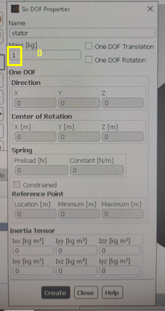
Further in the fluent I also chose passive and active elements, active blades, passive rotor and stator. For the rotor and stator in 6YUDF, I did not set the mass, I think this is not critical, for the blades I approximately indicated 1 kg:
But this calculation did not pass either, error "Negative volume".
I'm at a dead end, please tell me how to do it?
-
-
August 25, 2023 at 5:29 pm
javat33489
SubscriberGenerally understood. I redid everything, cut out the area in a different way. Added moment of inertia.
Everyone thinks everything is in order, BUT.
My wheel spins water from two circuits (inside and outside), when the volume is removed from a solid body, a void remains between the shoulder blades, and the fluent separates these two areas into two bodies, respectively, and turns them differently. How to connect them? For the fluent to see it as one body?
I will create a new topic.
This one can be closed.
-
- The topic ‘The pump wheel does not rotate in the FLUENT dynamic grid’ is closed to new replies.


-
4643
-
1540
-
1386
-
1230
-
1021

© 2025 Copyright ANSYS, Inc. All rights reserved.

